Tray blocks
The culvert is a rectangular reinforced concrete tray, which is a reinforced concrete bracket. All elements involved in road construction are subject to strict quality requirements. For concrete trays they are contained in Series 3.503.1-66. The design drawings of this series define the dimensions of the concrete tray as length, width and section height.
The tray block is part of a carefully thought-out drainage system, which during the construction of any roads plays an important role in the organization of a surface drainage system to protect the roadbed from waterlogging and erosion by precipitation. The culvert block is designed for drainage in road and bridge structures, as well as for drainage of storm water in road and civil construction. Such trays significantly increase the service life of the roadway, depriving water of the opportunity to wash away and destroy the edge of the asphalt and prevent the embankment from crumbling and spreading. Such a tray does not require cast iron gratings; it is placed along the roads on both sides, providing drainage.
To achieve additional strength, tray blocks are made from heavy grades of concrete M200 and M300, and the specific class of water resistance and frost resistance is dictated by the conditions of a particular project. The tray blocks are designed to be resistant to environments aggressive to concrete and moisture during operation. Polymer concretes are often used in the lining of trays, which, due to their high wear resistance and water resistance, do not allow hydraulic structures to wear out under the influence of water flows with sand suspended in it.
The drainage block of the tray is made by vibration pressing. The blocks are reinforced with frames made of rods, steel class A-I, Ac-II, A-II, A-III. All reinforcement and embedded products are pre-treated against corrosion. Due to the reinforcement, the weight of the product becomes 950 kg. If we compare concrete culverts with similar products, it is worth noting that these products have a much longer service life. As practice has shown, reinforced concrete blocks of trays do not lose their appearance over time.
Marking of tray blocks
I conventionally designate tray blocks using letters and numbers, product type and standard size.
The brand and weight of the product are indicated on the side of the product.
Tray block quality control
Products that have passed quality control will last for decades without the need for repair or replacement, making the purchase guaranteed to be profitable. A batch of tray blocks is inspected and products containing the following defects are rejected:
During acceptance tests, the following parameters of tray blocks are controlled:
A batch of tray blocks must be accompanied by a technical passport, which indicates:
Transportation and storage of tray blocks
Blocks of trays are stored in stacks no more than 2.5 meters high, with spacers placed between them in areas where there are mounting loops.
TYPICAL TECHNOLOGICAL CARD (TTK)
PRODUCTION OF WORKS ON THE CONSTRUCTION OF A PRECASTIC CULVER WITH AN HOLE OF 3.0x2.0 m WITH MONOLITHIC ENDS
I. SCOPE OF APPLICATION
I. SCOPE OF APPLICATION
1.1. A standard technological map (hereinafter referred to as TTK) is a comprehensive regulatory document that establishes, according to a specific technology, the organization of work processes for the construction of a structure using the most modern means of mechanization, progressive designs and methods of performing work. The TTK is designed for some average conditions of work. The TTK is intended for use in the development of Work Projects (WPP), other organizational and technological documentation, as well as for the purpose of familiarizing (training) workers and engineers with the rules for carrying out work on the construction of reinforced concrete, prefabricated culvert with a hole of 3.0x2.0 m with monolithic caps for the embankment of the highway.
1.2. This map provides instructions for the construction of a culvert using rational means of mechanization, provides data on quality control and acceptance of work, industrial safety and labor protection requirements during the production of work.
1.3. The regulatory basis for the development of a technological map is: SNiP, SN, SP, GESN-2001 ENiR, production standards for material consumption, local progressive standards and prices, labor cost standards, material and technical resource consumption standards.
1.4. The purpose of creating the TC is to describe solutions for the organization and technology of construction work in order to ensure their high quality, as well as:
- reducing the cost of work;
- reduction of construction duration;
- ensuring the safety of work performed;
- organizing rhythmic work;
- unification of technological solutions.
1.5. On the basis of the TTK, as part of the PPR (as mandatory components of the Work Project), Working Technological Maps (RTC) are developed for the implementation of certain types of work on the construction of a culvert. Working technological maps are developed for the specific conditions of a given construction organization, taking into account its design materials, natural conditions, the available fleet of machines and building materials tied to local conditions. Working technological maps regulate the means of technological support and the rules for performing technological processes during the production of work. Design features for the construction of a culvert are decided in each specific case by the Working Design. The composition and degree of detail of materials developed in the RTK are established by the relevant contracting construction organization, based on the specifics and volume of work performed.
Working flow charts are reviewed and approved as part of the PPR by the head of the General Contracting Construction Organization, in agreement with the Customer's organization, the Customer's Technical Supervision.
1.6. The technological map is intended for work producers, foremen and foremen performing construction work, as well as technical supervision workers of the Customer and is designed for specific conditions of work in the third temperature zone.
II. GENERAL PROVISIONS
2.1. A technological map has been developed for a set of works for the construction of a culvert.
2.2. Work on the construction of a culvert is carried out in one shift, the duration of working hours during a shift is:
Where 0.828 is the coefficient of use of mechanisms over time during a shift (time associated with preparation for work and carrying out technical maintenance - 15 minutes, breaks associated with the organization and technology of the production process and driver rest - 10 minutes every hour of work).
2.3. The work performed sequentially during the construction of a culvert includes:
- preparatory work;
- marking works;
- excavation;
- installation work (installation of the outlet head, installation of the foundation for the pipe body, installation of pipe sections, installation of the inlet head);
- waterproofing works;
- strengthening works.
2.4. The technological map provides for the work to be carried out by an integrated mechanized unit with automobile jib crane KS-4561A(see Fig. 1 and Fig. 2) with a lifting capacity of 25.0 tons as a driving mechanism.
Fig.1. General view of the KS-4561A truck crane
Fig.2. Height and load characteristics of the KS-4561A crane
2.5. Work should be performed in accordance with the requirements of the following regulatory documents:
- SP 48.13330.2011. Organization of construction;
- SNiP 3.01.03-84. Geodetic work in construction;
- SNiP 3.02.01-87. Earthworks, bases and foundations;
- SNiP 3.06.04-91. Bridges and pipes;
- SNiP 3.03.01-87. Load-bearing and enclosing structures;
- SNiP 3.04.01-87. Insulating and finishing coatings;
- SNiP 3.04.03-85. Protection of building structures from corrosion;
- Manual for SNiP 3.02.01-83*. A manual for the execution of work when constructing bases and foundations;
- VSN 32-81. Waterproofing of bridges and pipes;
- SNiP 12-03-2001. Occupational safety in construction. Part 1. General requirements;
- SNiP 12-04-2002. Occupational safety in construction. Part 2. Construction production;
- RD 11-02-2006. Requirements for the composition and procedure for maintaining as-built documentation during construction, reconstruction, major repairs of capital construction projects and requirements for inspection reports of work, structures, sections of engineering support networks;
- RD 11-05-2007. The procedure for maintaining a general and (or) special log of work performed during construction, reconstruction, and major repairs of capital construction projects.
III. ORGANIZATION AND TECHNOLOGY OF WORK EXECUTION
3.1. In accordance with SP 48.13330.2011 “Construction Organization”, before the start of construction and installation work at the site, the Contractor is obliged to obtain from the Customer in the prescribed manner design documentation and permission to carry out construction and installation work. Carrying out work without permission is prohibited.
3.2. Before the start of work on the construction of a culvert, it is necessary to carry out a set of preparatory work and organizational and technical measures, including:
- appoint persons responsible for the quality and safety of work;
- conduct safety training for team members;
- place the necessary machines, mechanisms and equipment in the work area;
- arrange temporary driveways and entrances to the work site;
- provide communication for operational dispatch control of work;
- install temporary inventory household premises for storing building materials, tools, equipment, heating workers, eating, drying and storing work clothes, bathrooms, etc.;
- provide workers with tools and personal protective equipment;
- prepare places for storing materials, inventory and other necessary equipment;
- fence the construction site and put up warning signs illuminated at night;
- provide the construction site with fire-fighting equipment and alarm systems;
- draw up a report on the readiness of the facility for work;
- obtain permission to carry out work from the Customer’s technical supervision.
3.3. Before the construction of the pipe begins, the following activities and work must be completed:
- a construction site prepared for work has been accepted from the customer;
- construction materials, necessary equipment, tools, reinforced concrete pipe sections were delivered and stored;
- entrances and exits from the site have been arranged;
- water drainage from the work site is ensured;
- a geodetic breakdown of the pit contour was carried out.
3.4. Reinforced concrete structures delivered to the construction site (see Fig. 3) are unloaded from vehicles using a KS-55713-4 truck crane.
Fig.3. Construction site plan
1 - fittings; 2, 3 - lumber warehouse; 4 - path of movement of the crane; 5 - warehouse block of pipe links; 6 - container with cement; 7 - concrete mixer; 8 - water tank; 9 - power plant; 10 - crushed stone warehouse; 11 - sand warehouse
The pipe sections delivered to the construction site are laid in one tier on a sand bed. Throwing pipe sections from vehicles or into pits is prohibited. The pipes are laid along the pipe pit, in accordance with the technological installation sequence, leaving a berm at least 4.0 m wide for the crane access.
The mounting loops on the pipe body links are cut off flush with the concrete surface by electric welding before the pipe is installed. cutting off hinges with a chisel or bending them is not allowed.
To ensure the drainage of water from the work site, the existing watercourse is directed to bypass the installation site - the pit under the pipe body.
3.5. Geodetic alignment works
3.5.1. The geodetic layout of the pit consists of marking it on the ground. The breakdown is carried out in two planes: horizontal and vertical. When laying out horizontally, the position of the axes is determined and fixed on the ground, and when laying out vertically, the estimated depth of laying the pipe.
3.5.2. Laying out a pit for a pipe begins with finding and securing the longitudinal axis of the pipe, performing the following steps:
- restore the road axis;
- measure with a steel tape (twice) the distance from the PC to the longitudinal axis of the pipe along the axis of the road;
- hammer a steel nail 100-120 mm long into the resulting point;
- center the theodolite over the nail and transfer to reality the angle between the axis of the pipe and the axis of the road;
- secure the resulting longitudinal axis of the pipe with four control posts, two on each side, installed no closer than 3 m from the boundaries of the pit;
- transfer the mark of the nearest benchmark to the control posts, as well as the marks of the pipe inlet and outlet trays;
- check the compliance of the future channel of the drainage ditch with the project;
- break out the outlines of the pit according to the layout drawing, securing its contours. To do this, cast-offs are installed parallel to the axes of the pit at a distance of 2-3 m from its boundary (see Fig. 4), the position of which is recorded in the layout drawing. On the cast-offs, use a tape measure to mark the main axes of the pipe, fixing them with marks and corresponding inscriptions.
Fig.4. Inventory cast-off
2 - steel wire string; 3 - plumb line
3.5.3. The surveyor, using a theodolite, transfers the axle alignments to the upper edge of the cast-off and secures them with marks. The breakdown of places where scratches are applied is carried out using the method of opening serifs from the axes X And Y center grid available in the working drawings. Per relative mark 0,000
The elevation of the top of the pipe was adopted corresponding to the absolute elevation available on the general plan. The position of the centering axes of the pipe is fixed with steel wire strings stretched on a cast-off. Then they are transferred to the surface of the platform using plumb lines lowered from the stretched strings and this point is secured with metal pins. The accuracy of the planned pit layout must be within 5 cm. The securing marks (pegs with marks) are retained until the pipe is put into operation by the customer. Alignment points damaged during the work must be immediately restored.
The accuracy of marking work must comply with the requirements of SNiP 3.01.03-84 and SNiP 3.02.01-87. The diagram for the production of geodetic pit layout is shown in Fig. 5.
Fig.5. Scheme of production of geodetic pipe laying
3.6. Pit development
3.6.1. The development of a pit for the pipe body and head is carried out single-bucket excavator ET-16(see Fig. 6), a special swamp modification, the pressure of which on the ground does not exceed 20-25 kPa, having a widened and elongated caterpillar track. Detected underground water outlets into the pit (springs, springs, etc.) are plugged with a clay plug.
Fig.6. Excavator ET-16
Cleaning and leveling of the bottom of the pit to the design marks (5-10 cm) is carried out manually, under the lath, taking into account the design slope and a given construction rise equal to 1/50 of the embankment height, immediately before the foundation is laid.
The excavated soil is placed in a dump and then removed beyond the construction site. The bottom of the pit is compacted vibrating plate LF-70, up to 0.95.
A break between the completion of the pit development and the installation of the foundation for the pipe body is, as a rule, not allowed.
If the construction of the foundation is delayed, it is necessary to develop the pit short of the design mark, and cover the pit itself with heat-insulating material. When using peat (0.16-0.18 g/cm), layout, leveling and compaction are done manually. Insulating blocks made of aerated concrete, polystyrene foam, etc. laid with a truck crane. The completed work is presented to the Customer for signature on the construction of the pit, in accordance with Appendix 3, RD-11-02-2006.
3.7. Installation of a monolithic concrete foundation slab for the pipe body
3.7.1. Under prefabricated reinforced concrete pipe sections, it is necessary to build a foundation in the form of a monolithic slab of concrete class. B20, W6, F150 0.20 m thick per layer crushed stone M 800 fraction 20-40 mm thickness 0.10 m.
Crushed stone is being delivered front loader VOLVO L-45B(bucket capacity 1.2-2.5 m), leveled by hand, compacted vibrating plate LF-70D up to no less than 0.95.
The completed work is presented to the Customer for signing inspection reports of hidden work on the installation of a “cushion”, in accordance with Appendix 3, RD-11-02-2006.
3.7.2. To install a monolithic concrete slab, a prefabricated formwork 20 cm high is installed on the finished “cushion”. The marking of the formwork installation sites is carried out using the method of opening notches from the axial points of the pipe. The anchor points are fixed to cast-offs located outside the work area. Per relative mark 0,000
The elevation of the top of the pipe was adopted, corresponding to the absolute elevation indicated on the general plan. The formwork is assembled from edged softwood lumber from the 6th century. 40-50 mm thick and bars 40x40 (50x50) mm. On the inside, the boards are fixed to the required size with spacers, and on the outside with stakes driven into the ground close to the boards, which, just like the boards, perceive the lateral pressure of the concrete mixture.
3.7.3. Wooden “beacons” 30 mm high are installed on the compacted crushed stone “cushion” and on them, to give strength to the monolithic foundation, meshes of reinforcing steel A-III, grade 35GS, with a diameter of 12 mm, with a cell pitch of 100x100 mm, are laid. The grids are laid with an overlap of at least 25-30 reinforcements. The mesh is connected by tying the joint in three places (in the middle and at the ends) with knitting steel wire with a diameter of 0.8...1.0 mm using special hooks.
The reinforcing mesh is supplied to the work area using a truck crane. Manual installation is allowed only if the weight of the reinforcement elements is up to 20 kg.
3.7.4. The process of laying concrete mixture consists of work operations associated with feeding it into the formwork and compaction. Before laying the concrete mixture into the formwork, you must check:
- formwork fastening elements;
- quality of cleaning the formwork from debris and dirt;
- quality of cleaning of fittings from rust deposits;
- carrying out the axes of the structure (with paint) onto the reinforcement frame;
- use slats or tow to seal large gaps in the formwork;
- cover the internal surfaces of the formwork with polyethylene film to reduce the adhesion force of concrete to boards;
- present the finished formwork and installed reinforcing mesh with outlets to the Customer for inspection and signing of the Certificate for hidden work on the installation of formwork and installation of the reinforcement cage, in accordance with Appendix 3, RD-11-02-2006.
3.7.5. The concrete mixture is delivered to the site concrete mixer trucks SB-049A(4.0 m) and unloaded into rotating tubs with a capacity of 0.8 m located within the range of the crane, after which the tub is installed in a vertical position using a truck crane, transported to the laying site and unloaded into the formwork.
3.7.6. When laying the concrete mixture, you must follow the basic rules:
- adding water when laying the concrete mixture is not allowed;
- cold water separated from the mixture must be removed;
- the height of free dumping of the concrete mixture should not exceed 1.0 m.
When laying the concrete mixture, it is necessary to provide protection of the structure being manufactured from precipitation with polyethylene film.
Stripping a concreted structure and loading it with pipe links is allowed when the concrete reaches a strength equal to at least 75% of the design strength.
3.8. Monolithic head structure
3.8.1. Operations for constructing monolithic concrete heads are performed in the following order:
- a pit is being developed for the portal wall and slope wings;
- install the formwork of the portal wall with the adjustment of the panels and their fastening;
- install the formwork of the left slope wing with plumb alignment and fastening;
- install the formwork of the right slope wing;
- take the concrete mixture from a bucket supplied by a truck crane;
- place the concrete mixture into the formwork and compact it with a vibrator;
- smooth the exposed surface of the freshly laid mixture;
- maintain concrete.
3.8.2. The excavation for the heads is being developed single-bucket excavator ET-16. Cleaning and leveling the bottom of the pit to the design marks (5-10 cm) is done manually. The excavated soil is placed in a dump and then removed beyond the construction site. The bottom of the pit is compacted vibrating plate LF-70, up to 0.95. Crushed stone is poured into the pit under the head with a design layer, taking into account the safety factor for compaction equal to 1.25, leveled and compacted with a vibrating plate.
3.9. Installation of collapsible formwork under the heads
3.9.1. Formwork is used to give the required shape, geometric dimensions and position in space of the erected heads (portal wall and slope wings) by laying the concrete mixture into the volume limited by the formwork.
3.9.3. Formwork panels are made from edged lumber 50 mm thick, 100 mm wide and wooden blocks 50x50 mm. The front parts of the boards in contact with the concrete are sheathed with waterproof, bakelite, laminated plywood 16 mm thick (FBS-16), secured to the boards with self-tapping screws.
3.9.4. For concreting the heads, collapsible formwork is used. Collapsible formwork is assembled from ready-made elements - panels. The assembly of formwork panels is carried out at the installation site in a certain sequence:
- the boards are laid with the working surface down, wooden slats are placed in the places where mounting and working fasteners are installed;
- check the overall dimensions of the shields, nail limiting wooden bars along their contours;
- the boards are connected to each other with wooden overlays;
- holes with a diameter of 18-20 mm are drilled in wooden slats in places where the ties pass;
- wooden scrums are laid out on top of the shields;
- fights with shields are connected with nails or staples;
- rigidity bonds are laid on top of the contractions perpendicular to them, for which the same contractions are used;
- struts are attached to the lower tiers of the contractions or stiffeners, ensuring the stability of the panels in a vertical position.
3.9.5. Installation of formwork panels in the design position is carried out according to the marks marked on the crushed stone preparation according to the alignment axes fixed on the cast-off, with simultaneous alignment of the verticality of the panels along the alignment axes with theodolites.
The formwork installation site is cleared of wood chips, debris, snow, and ice. When installing shields, you need to ensure that they are tightly connected to each other. When installing the formwork, it is necessary to ensure its stability with the help of racks, resting them on a solid base and securing them with spacers.
Prefabricated reinforced concrete pipes, depending on the cross-section, are divided into round cylindrical, round with a flat base, rectangular and ovoid (Fig. 7.4).
Circular culverts used when the embankment height is predominantly no more than 8 m. Round pipe links under railway embankments rest on shallow or deep foundations, prefabricated, prefabricated monolithic or monolithic. The design of the pipe foundation depends on the bearing capacity of the foundation soil. g - ovoidal; new; prefabricated reinforced concrete pipes: a - round, rectangular and ovoid, fig. 0 0 0 0 0 0 0 0 0 0 0 0 0 0 0 0 0 0 0
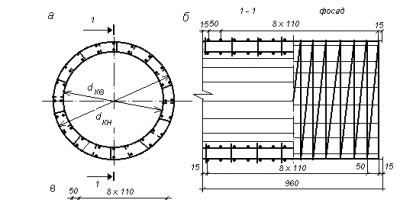
When supporting a round cylindrical link on a flat foundation, a pattern block is used (Fig. 7.5).
Reinforcement cage of round links consists of two rows (external and internal) of working spiral reinforcement, transverse reinforcement - clamps, as well as distribution longitudinal reinforcement (Fig. 7.6).

Rice. 7.6. Diagram of the reinforcing cage of a round pipe for a link 1 m long: A– cross section; b– view 1-1 and facade; V– spiral; d k– frame diameter; d H k , d B k– diameter of the location of the outer and inner spirals
The reinforcement cage consists of the same number of spirals located along the outer and inner contours of the link, which is determined by calculation. The Lengiprotransmost Design Institute has developed the following standard designs for reinforced concrete round pipes:
№GS 3.501.1-144– round reinforced concrete culverts for railways and roads;
№GS 3.501.1-144. Issue 0-1. Inv. No. 1313/2– round reinforced concrete culverts with flat support for railways in normal climatic conditions.
Z
Rice. 7.7. Reinforcement scheme for a round link with a flat base: A– cross section; b– view along the pipe axis; d kv ,
d book– diameters of internal and external frames
Links round pipes with flat base have more economical reinforcement, the diagram of which, according to the developments of Lengiprotransmost, is presented in Fig. 7.7.
Design of inlet and outlet heads reinforced concrete Round pipes are assumed to be the same from the unification conditions. The heads consist of slope walls (wings), located at an angle to the pipe axis, and portal walls (Fig. 7.8).
Reinforcement frame of slope wings made from meshes (Fig. 7.9).

Rice. 7.8. Round pipe head design: A– façade; b – section along the pipe axis; V - plan (embankment not shown); 1 – conical link; 2 – portal wall, 3 – slope wall; 4 – pattern block; 5 – foundation

Rice. 7.9. Design of the reinforcement frame of the slope wings of the round pipe head: A - facade; b – plan
The slope walls of the heads are installed on reinforced concrete slabs laid on crushed stone or gravel-sand preparation. A concrete tray is placed between the slope wings on a gravel-sand preparation (see Fig. 7.8).
WITH
Rice. 7.10. Diagram of a rectangular reinforced concrete pipe section: A– cross section; b– cut along the pipe axis
The standard design provides for an increase in elevated links by 0.5 m compared to normal ones. The following standard designs of prefabricated reinforced concrete pipes of rectangular cross-section have been developed:
№GS 3.501-177.93– reinforced concrete rectangular culverts for railways and highways (JSC Transmost, 1994);
№GS 3.501-177.93. Issue 0-2– rectangular pipes for railways in moderate and severe climatic conditions (JSC Transmost, 1994);
№GS 3.501-107. Inv. No. 1130/1.2– rectangular concrete culverts for railways and roads.
Reinforcement frame of a rectangular pipe link includes meshes consisting of working and distribution reinforcement, located along the external and internal contours, taking into account the provision of a protective layer of concrete, which are combined using clamps (Fig. 7.11).

Rice. 7.11. Reinforcement frame diagram of a rectangular link: A– cross section; b– view along the pipe axis
In the middle part of typical pipe structures, the length of the sections is 2.01 and 3.02 m. The links rest on the foundation along a layer of cement mortar. The foundations of the sections can be monolithic, prefabricated reinforced concrete or concrete blocks, shallow or deep. An expansion joint 3 cm thick is installed between the sections.
In reinforced concrete pipes of rectangular cross-section, they are used bell heads with sloped wings located at an angle of at least 20° (Fig. 7.12).
On railways built in areas with harsh climatic conditions, rectangular reinforced concrete and concrete culverts are most common. Currently, standard designs of rectangular pipes for harsh climatic conditions have been developed:
№GS 3.501.1-177.93. Issue 0–3. Pipes for railways and roads in particularly harsh climatic conditions. (JSC Transmost, 1994);
№GS 3.501-65. Inventory No. 1016. Culverts for railways and roads at a design temperature of minus 40 o C and below, deep seasonal freezing and ice dams. Rectangular concrete pipes. (Lengiprotransmost, 1976).

Rice. 7.12. Design of the outlet head of a rectangular pipe: A - facade; b – section along the pipe axis; V - plan (embankment not shown)
Links rectangular reinforced concrete pipes used with a hole from 1.5 to 6.0 m. They are based on prefabricated monolithic foundations, consisting of prefabricated reinforced concrete blocks of L- or T-shape (Fig. 7.13, 7.14) and monolithic concrete, as well as deep foundations on piles and pillars (Fig. 7.15, 7.16).

Rice. 7.13. Rectangular reinforced concrete pipe with L-shaped and T-shaped foundations: A - section cross section; b– head façade

Rice. 7.15. Rectangular reinforced concrete pipe with foundations on piles and pillars: A - head; b, c – cross section of sections

Rice. 7.16. General view of a rectangular reinforced concrete pipe with foundations on piles
Concrete rectangular pipe structures used with a hole from 1.5 to 6.0 m, which provide a water throughput capacity of up to 150 m 3 /s. The middle sections of the pipes are 3–4 m long. The structures of such pipes consist of reinforced concrete floor slabs, concrete wall blocks, nozzles, a tray and a foundation (Fig. 7.16, 7.17). Pipes with a hole of 1.5–3.0 m have solid foundations, and the rest are separate on a natural foundation, monolithic, prefabricated, and also deep laid on piles or pillars. The trays are concreted using sand preparation. The pipes have bell-shaped ends with increased inlet and normal outlet links.
Typical concrete culverts have similar foundations to reinforced concrete ones (Fig. 7.17, 7.18).

Rice. 7.17. Rectangular concrete pipes: a, b – cross section of section and head; V - with L-shaped and T-shaped foundations
In the typical design of rectangular culverts, foundations made of reinforced concrete blocks of L-shaped and T-shaped sections are provided for a freezing depth of the foundation soil equal to 2.3 and 4 m.
In harsh climatic conditions, in the presence of thawed and soft soils at the base, it is preferable to install the outer sections and head openings on pile foundations (see Fig. 7.16). The use of pile foundations increases the rigidity of the base and protects pipes from stretch marks. In case of weak foundation soils, it is advisable to use foundations with inclined piles in the outer sections and head openings.
When constructing culverts on permafrost soils, the natural regime of the foundation is maintained without disturbing natural conditions. In this case, preference is given to pipes with foundations on drilled columns with a diameter of 0.6–0.8 m (see Fig. 7.15, V).

Rice. 7.19. Design of the head of a concrete pipe with an ovoid cross-section: A - cross section; b– façade; 1 – opener section; 2 - general form
Structures of concrete and reinforced concrete pipes ovoid section used with a hole from 1.0 to 3.0 m (Fig. 7.19, 7.20). Reinforced concrete links of ovoidal pipes have reinforcement in the form of closed spirals (Fig. 7.21).This type of reinforcement cage ensures reliable operation of the structure taking into account the full range of loads. All sections of ovoidal pipe links operate as eccentrically compressed elements.
The use of concrete ovoidal pipes makes it possible to reduce the labor intensity of factory production and the consumption of reinforcing steel. They are used for embankment heights of up to 20 m.
Reinforced concrete pipes with an ovoid cross-section are more efficient structures when compared with round structures in terms of reinforcement consumption on average up to 40–45%.
Add to bookmarks
The construction of pipes is prohibited if there is ice and ice drifts. On streams and rivers that have fish spawning grounds, the installation of pipes is possible only with the permission of the fisheries inspection.
The elevation of the edge of the soil at the approach to the pipe above the calculated level of the water base is taken to be no less than 0.5 mA, and for a pipe with pressure or semi-pressure mode, no less than 1 mA.
The construction of pipe heads takes place from portal walls and a pair of slope wings, which are buried in the soil base below the freezing depth by 25 cm and installed on a base made of crushed stone materials having a thickness of 0.1 mA.
Natural soil below the freezing depth is replaced with a mixture of sand and gravel.
Pipes are divided into 3 groups according to their load-bearing capacity: the estimated height of the soil backfill is 2 m, 4 m, 6 m.
Under certain conditions, it is permissible to construct pipelines using pipes with other design heights and soil backfills.
Pipe brands consist of alphanumeric groups, which are separated by a hyphen. Moreover, the first group contains type designations, and the second contains diameters in centimes and useful length in decimes, as well as group numbers by load-bearing capacity.
The construction of pipes takes place in accordance with GOST 26633 from heavy concrete mixtures, where the compressive strength class is set to B 25. The concrete water resistance of the pipe must comply with W4.

Pipes TS, TB, TSP and TBP are supplied to consumers complete with sealing rings made of rubber material. Cracks on pipe surfaces are unacceptable, with the exception of a shrinkage width of no more than 0.05 mm.
Pipe heads with holes of 0.5...0.75 m are constructed from portal walls, which are buried in the ground below the freezing depth by 25 cm.
The wings of the slopes can be made of B15 grade monolith without reinforcement ties and taking into account the formwork size of the precast reinforced concrete block.
The length of the pipes (Ltr) is determined using the formula:
Ltr=v+2(n-s-d)hm,
where in is the width of the ground in max;
n is the bulk height in swing;
c is the wall thickness in max;
d—pipe opening in stroke;
m is the slope coefficient.
Technology for the construction of reinforced concrete pipes (reinforced concrete culverts)

Before installation, it is necessary to carefully check the pipes for permissible deviations in accordance with GOST.
- Check the pipe elements for permissible deviation according to GOST (the length of the links is 0-1 cm, the wall thickness is 0.5-1 cm, other measurements are approximately + 1 cm).
- Remove beads and concrete splashes on the connecting link elements.
- Select all pipe elements by brand according to the project solution.
- Store pipe elements in one place.
Preparatory work at the construction site:
- Select and prepare a site for construction. Uproot the bush and level it with the necessary equipment.
- Receive and place material, equipment and structures in designated locations.
- Break the pipe axis and the pit contour.
Surveying work, which is performed in the construction process, usually includes:
- arrangement of the structure in plans, taking into account the main axes and contours of the pit;
- altitude breakdown;
- leveling the longitudinal profiles of pipe trays.
The installation in the plans takes place with visible signs fixed in place, from which it is possible to accurately determine the location of the pipe and its component elements. Fastening usually occurs with the help of two pillars, which are installed along the longitudinal axes of the pipes, in order to ensure their safety for the entire construction period, and pegs driven along the bulk axes in the required places.
In some cases, at a distance of 150-200 cm from the boundary of the pit, cast-offs are constructed from boards installed horizontally, on which characteristic foundation points are marked. The boards themselves are nailed to posts that are fixed into the ground.
When planning a layout, strict adherence to the alignment position, which is located along the axes of the embankments, is necessary.
If any unfavorable soil or other factors are identified at the locations of pipes and heads, they must be shifted in the required direction. All differences from the existing project must be agreed upon with the design organizations and the customer, as a result of which the most suitable technology will be selected.
High-altitude technology is to determine the surface marks at the locations of the pipes and the depth of cutting the earth or, conversely, adding it under the pipes. Work on the ground associated with digging a pit and laying a foundation is carried out in the presence of instrumental control.
Using a level, the design corresponds to the actual mark of the excavated bottom and the cushion top. The height positions of the foundation, and subsequently the arrangement of pipes and caps, are controlled in the same way.
The longitudinal profiles of the pipe are leveled immediately before backfilling and backfilling of the bulk layer to the design marks. Necessary, periodic and long-term further observations are established in accordance with the required standards.
This technology is produced by tying it to benchmarks, which are located near the pipes.
Execution work

The foundation pit is obtained using an excavator.
Excavator digging and manual cleaning of pits.
Construction (if necessary) of a pit bottom with stone material by pressing using means of drowning.
The pit for the foundation, where the culverts will be located, is developed mainly without fences (fastenings). Only in water-saturated soil, with significant water inflows and the impossibility of ensuring the stability of the pit walls, is the ground developed taking into account fastening protection. Strengthening pits is applicable if there are operating structures nearby. This technology ensures their sustainability.
The pit outlines and the technology for their development depend on the designs of the pipes and their foundations, on the types and conditions of the earth. The steepness of the pit slopes is determined by taking into account the pit depth and the characteristics of the land being mined.
If the design provides for waterproofing or other work is carried out that is associated with the presence of people here, then the distance between the side surfaces of the foundation and the vertical walls of the pit is used to be at least 70 cm. When such work is not available, these parameters can be reduced to 10 cm.
When foundation concreting without formwork, the excavation size is taken equal to the size of the given foundation.
When developing pits with slopes, the gap between the foundation and the bottom of the slope must be at least 30 cm. When digging a pit, measures are taken to prevent them from filling with surface or groundwater. For these purposes, earthen ridges are poured along the pit contours. When constructing pipes on permanent watercourses, it is necessary to construct a dam or divert the channel to the side using a ditch.
If water does get into the pit, it needs to be removed or a descent into the ditch below must be arranged. This is usually possible during the construction of a sloped water pipeline or mechanized drainage system. In these cases, fenced pits are made at the bottom of the pit, from which water is pumped out using a pump. Such pits are located behind the foundation contour. They provide drainage during foundation work, right up to backfilling.
As the pit gets deeper, the pit fencing must be lowered. Non-rocky soils are excavated by earth-moving machines without disturbing the natural formations of soils in the foundations. The shortfall is 10-20 cm. The final cleaning of the pit occurs before laying the foundation.
Today, of the various variety of earth-moving machines, the most widely used in the construction of water pipelines on roads and railways are bulldozers and excavators.

The bulldozer is most popular when making pits.
Pit construction with bulldozers is most appropriate when laying the pipes and heads themselves at the same level or when there are minor differences.
For a pit that is not fenced, an excavator with a backhoe or dragline is used. The advantage of this mechanism is the ability to develop soil at different depths, which helps ensure the construction of pits under the middle parts of pipes and heads, the bases of which are laid at significant depths.
When developing a fenced pit, it is advisable to use grabs.
In all situations, the soil that is being developed is placed outside the pit at those distances that can ensure the stability of the walls or fences. Heaps of earth should not interfere with construction, installation and water flow.
Design and construction of the foundation

There is a small-block and large-block foundation.
When installing a foundation using prefabricated elements, you first need to lay the head blocks to the bottom level. Then the cavities of the foundation heads are filled to the same level. Subsequently, they are covered with local soil on three sides, and in places where foundations of different depths meet, with sand-gravel or sand-crushed stone mixtures, which must be compacted layer by layer and filled with cement mortar.
Then the foundation masonry and caps must be carried out taking into account section by section. Consecutive construction is required, from the exit heads to the entrance ones. Multi-row masonry is performed using suture dressing. To install a monolithic foundation you need:
- manufacture and install formwork;
- deliver ready-mixed concrete or prepare it on site;
- lay down the mixture;
- provide the necessary care, remove the formwork, fill the sinuses.
The simplicity of the foundation outlines makes it possible to produce formwork in the form of an inventory panel, which is used on many construction sites. The surfaces of such shields must be smooth. Before concreting, it is recommended to lubricate them with grease. This will make it easier to separate the panels from the concrete structure in the future.
In order to load concrete mixture into sectional formwork, it is necessary to use inventory trays or buckets, which are loaded on site or delivered from a concrete mixing station. Concrete compaction occurs using deep or surface vibrators.
The construction of a prefabricated monolithic foundation occurs in the following sequence: it is necessary to install formwork between sections on the prepared base or cushion, and pour concrete mixture into the available space.
The requirements for concrete work are the same as for constructing a monolithic foundation. Mechanisms and equipment for foundation devices must be selected taking into account all technological processes for pipe construction.
An approximate list of equipment is: crane, mortar mixer, concrete mixer, vibrator, electric rammer, welding unit, mobile power station.
You can increase efficiency when installing pipes if you organize the manufacturing processes, delivery of structures and installation of pipes on site, observing a single comprehensive schedule.
A prerequisite for these events is good access and developed construction bases. The foundation and the number of pipe heads in this situation are mounted “on wheels”. The necessary elements are removed from the vehicle by crane and placed in the structure.
The construction of a pile foundation is very common where there is weak soil. The driving of piles occurs mainly with units that include driving equipment on the bases of tractors, truck cranes or excavators.
Culvert reinforced concrete pipes: installation
Prefabricated pipe heads and bodies begin to be installed after the foundation structure and axillary backfill.
Before installation, the foundation blocks, caps, and links must be cleared of dirt, and in winter conditions, of ice and snow.
The link or blocks that have a flat surface on the bottom edges must be installed on cement mortar. Cylindrical links must be installed on wooden supports, maintaining the required gaps between them and the foundation. Subsequently, a concrete mixture is tamped under the links, thereby ensuring full contact of the links over the entire distance.
The solution must be added from one side, while monitoring its appearance on the other. Then the missing solution is replenished from the opposite side. This ensures complete alignment and filling of the seams. The solution is needed with a mobility of about 12 centimes.
By filling vertical and horizontal joints, it is possible to ensure a continuous and monolithic pipe structure in the area where expansion joints are present.
Joint seams on pipe links or sections are caulked on all sides with tow, which is impregnated with a bitumen mixture. On the inside, the seams must be sealed to a depth of 0.03 m using cement mortar.
The entire installation process is carried out in compliance with the design gaps between the links and blocks in order to maintain the sectional size and prevent overlap of the expansion joint.
Waterproofing and pipe installation
The main type of reinforced concrete insulation today occurs using bitumen mastic.
Coverings are made non-reinforced (coated) and reinforced (pasted). Coating waterproofing is two layers of bitumen mastic, each having a thickness of 1.5-3 mm over a soil layer.
Reinforced waterproofing consists of material layers between three layers of bitumen mastic over a primer layer.
The surfaces of reinforced concrete pipes and their elements (links, floor slabs, nozzles, etc.) are usually protected with glued insulation.
Waterproofing: work sequence
- surface preparation;
- actual waterproofing;
- installation of protective layers.
During surface preparation when working with a structure, it is necessary to clean it from dirt, dry it, and in some situations it is necessary to level it with cement mortar.
It is necessary to apply a preparatory layer of cement mortar where internal corners are formed, for example, on the ceilings of pipes and heads in front of cordon stones, for a drain device in a multi-point pipe, etc.
The first technological operation is waterproofing, that is, it is necessary to apply bitumen varnish to the insulated surfaces, which acts as a primer in order to fill small cracks and pores. In addition, it improves the adhesion of bitumen mastic and the concrete surface.
There are also non-mechanized methods of priming devices using brushes.
Non-reinforced waterproofing is installed after the primer has dried, but not less than 24 hours after application.
Hot mastic is applied in layers 1.5-3 millimeters thick, and the next layer after the first one has cooled. For these purposes, hand tools (spatula, etc.) are used. You can improve the quality of work and reduce labor costs if you use mechanized methods, mainly using pneumatic spraying.
Reinforced waterproofing is arranged in this way: first, one layer of hot bitumen is applied and a layer of one of the roll materials is glued. The same is repeated for subsequent layers. The layer that will be the last needs to be covered with mastic to a thickness of 1.5-3 mm and leveled using a manual electric roller; if necessary, add places where there is insufficient waterproofing.
The individual panels are overlapped with a 10-centimeter overlap. The first and second joint should not be one above the other. Subsequent joints are made with a shift of no less than 0.3 m relative to the joints of previously laid layers.
The rolled material is glued without the formation of bubbles, and a tight fit of the material is required on all surfaces. Waterproofing is smoothed using electric irons and electric rollers.
The installation of protective layers is necessary to ensure that the waterproofing is not subject to mechanical damage during backfilling, given that it is one of the important elements during long-term operation and normal operation of pipes.
Backfill
Reinforced concrete culverts must be covered with soil after all construction work has been completed and the corresponding acceptance certificate has been issued.
The same soil from which the embankment was built is suitable for these purposes.
Bulk construction over culverts is divided into two stages:
- Fill the gaps between the foundation and the walls of the pit with soil.
- Backfill the pipes at the unit height.
The soil is laid simultaneously on all sides of the pipe to an equal height and compacted with special soil-compacting vibro-impact machines, and in their absence, pneumatic rollers are used. The soil prism is poured using inclined layers, the thickness of which is determined taking into account current standards.
When moving along a separate soil layer along pipes, the machine should start working from a remote area, gradually approaching the pipes themselves. It is possible to compact the soil directly near the pipes themselves if on the opposite side there is already a layer of earth of the same level poured along the entire length of the pipes. In this case, special attention is paid to soil compaction near the pipe walls. Here, the manual electric rammer should be located no closer than 0.05 mA from the wall.
It is prohibited to over-compact the soil above the middle parts of the pipes in order to subsequently avoid structural overloads. For significant bulk heights of more than 10 m above the pipes, it is recommended to leave a zone where the density is reduced. Next, level the ground using a bulldozer without compaction.
If, during construction, equipment that moves over or near buried structures is heavier than the live loads, then additional backfilling is required to avoid damage to the pipe.
The degree of soil compaction within the prismatic limits of the backfill is assessed using the coefficient K, which determines the ratio of the density that has been achieved to the standard maximum (determined by the standard compaction method). The latter is given in the production working design, which includes data from geological and engineering surveys. The current instructions require that the compaction coefficient be ensured at least 0.95. Density control is carried out using a Kovalev moisture meter-density meter. It should be said that in pipe filling processes, deviations from K, which is equal to 0.95, in the smallest direction are prohibited. Indeed, as the density of the earth decreases, the deformation modulus and load-bearing capacity of the pipes significantly decrease.
Safety precautions (TB)
Only those workers who have passed the necessary medical examination and introductory (general) TB training and TB training directly at the place of work can be hired for this job.
In addition, employees are required to learn safe working methods within three months from the start of work using a program lasting 6-10 hours. After completing the training, you must pass an exam in a permanent commission, based on the results of which a report will be drawn up, which must be included in the employee’s personal file.
The construction site must have permanent or temporary sanitary facilities: latrines, washrooms, locker rooms, clothes dryers, eating areas, showers, first aid stations or first aid kits. Workers must be provided with drinking water.
The construction administration must provide workers with special clothing, footwear and personal protective equipment in accordance with current standards.
Construction workers need:
- carry out correct and safe construction and installation work;
- monitor the condition of scaffolding and scaffolding, protection devices, foundation pits, etc.;
- check the cleanliness and order of work places, access roads and passages,
- ensure illumination of work places, check the correct operation of hoisting and crane roads;
- instruct employees on TB in the workplace;
- control the application and correct use of personal protective equipment and protective clothing by employees;
- monitor compliance with heavy lifting standards, provide workplaces with posters and inscriptions.
CENTRAL INSTITUTE REGULATORY
RESEARCH AND SCIENTIFIC AND TECHNICAL
INFORMATION"ORGTRANSSTROY"
MINISTRY OF TRANSPORT CONSTRUCTION
TEAM DEVICE
REINFORCED CONCRETE CULVER
DIAMETER 1 m UNDER THE ROAD
I. SCOPE OF APPLICATION
The technological map was developed taking into account progressive methods of organizing construction and production of work, as well as methods of scientific organization of labor and is intended for use in developing a project for the production of work and the organization of work and labor at the site.
The technological map provides for the construction of a single-point prefabricated reinforced concrete pipe with a diameter of 1 m, length 26.28 m under a highway (with an embankment height of 4 to 7 m).
The design of the pipe was adopted according to the “Standard design (501 Ж-5) of prefabricated unified concrete culverts for railways and roads” of Glavtransproekt, approved by order of the Ministry of Railways and the Ministry of Transport of July 8, 1966 No., inv. No. 101/1.
The pipe is mounted from prefabricated reinforced concrete elements:
the foundation is made of patterned blocks laid over crushed stone preparation;
pipe body - from links 1 long m;
heads with openers - from separate blocks.
Strengthening the riverbed at the heads is not provided for in the technological map.
In all cases of using a technological map, it is necessary to link it to local conditions of work.
II. INSTRUCTIONS FOR PRODUCTION PROCESS TECHNOLOGY
The pipe construction work includes:
preparation of the construction site;
marking works;
reception and placement of equipment, materials and structures at the construction site;
construction of a pit for the foundation of pipes and heads;
crushed stone preparation device;
installation of foundation blocks, pipe heads and links;
filling the cavity of the pit with soil;
concreting trays within the caps;
waterproofing works;
backfilling the pipe with soil.
Construction site preparation
A site in the pipe construction zone (at a distance of at least 10 m in each direction from the pipe axis) are planned with a bulldozer, giving slopes to ensure water drainage from the pipe.
At the exit head the natural channel is cleared, and at the entrance head at a distance of at least 1.5 m from the contour of the pit, they block the channel with soil and arrange a bypass ditch or embankment of the construction site. These measures must ensure complete drainage of surface water from the pit.
For the delivery of equipment, concrete blocks and materials, access roads are cleared and planned with a bulldozer, ensuring free passage along the ring traffic pattern.
Marking work
The position of the pipe is determined by the road design. The design organization must fix in kind and hand over to the work contractor the point of intersection of the road axis with the longitudinal axis of the pipe, the longitudinal axis of the pipe, secured with four outrigger stakes (Fig.), as well as a high-altitude benchmark.
By taking measurements along the axis of the pipe, the outline of the pit is outlined and marked with pegs.
At a distance of 1 m from the boundaries of the pit, they arrange a cast-off of boards or beams (Fig.) and mark on it the longitudinal axis of the pipe and the position of the heads, openings, and foundation sections.
If possible, the cast-off should be buried in the ground to protect it from damage by a bulldozer or excavator.

Sequence of installation of blocks and pipe sections
|
Crane parking |
Mounting number |
Element Marne (Block No.) |
Block weight, T |
Maximum boom reach, m |
|
|
Installation of output head blocks (portal and openings) |
|||||
|
Device for gravel and sand preparation for the outlet head |
|||||
|
Laying a patterned foundation block |
|||||
|
Installation of conical link and pipe links |
|||||
|
Laying patterned foundation blocks |
|||||
|
Installation of pipe sections |
|||||
|
Laying pattern blocks |
|||||
|
Installation of pipe sections |
|||||
|
Installation of inlet head blocks |
|||||
|
Device for gravel and sand preparation under the entrance head |
|||||
|
Installation of patterned foundation blocks |
|||||
|
Installation of pipe links and conical link |
|||||
Installers 4 grades - 1st and 3rd grade. - 1 take blocks and links and install them using guy ropes and crowbars in the design position.
Installer 3 raz. inspects and cleans blocks and links, slings them for feeding into the pit. Installer 2 jobs fills the vertical seams of the patterned foundation blocks with sand-cement mortar before installing the links. After installing and unfastening the head blocks, the entire team carries out work to fill the space behind the portal block and the base for the trays with a gravel-sand mixture.
Before installing the last links of the pipe, the installer 2 r. proceeds to pour cement mortar under the pipe links using a flat funnel (see. rice.). He finishes the work immediately after installing the last links of the pipe. Then he moves on to another pipe.
The insulator workers, working two at a time on each head, concrete the trays at the outlet and inlet heads. The concrete mixture is delivered by dump trucks and unloaded onto sand and gravel preparation, spread with shovels in an even layer and compacted with a surface vibrator. The surface of freshly laid concrete is smoothed with trowels and covered with sand. Immediately after installing the trays, the working units fall asleep simultaneously on both sides of the pit cavity. The soil is pushed with a D-271 bulldozer, tossed manually in hard-to-reach places, and then distributed with shovels in an even layer in the axles of the pit and compacted with electric rammers S-690. The insulator team also carries out work on sealing seams between the links and head blocks, arranging lining and coating waterproofing of the pipe, as well as backfilling the pipe with soil to a height of 0.5 m.
Two waterproofers 3 and 2 grades. They make bundles of tow, dip them in bitumen and caulk the seams between the links. Then they begin caulking the seams from the inside with cement mortar and jointing the joints. They work from the middle of the pipe to the edges, installing light portable circles under the top of each seam (see Fig.), supporting the solution in the seam.
Following them are two waterproofers of 4 and 2 grades. arrange adhesive insulation of seams. To do this, one cuts panels of bituminized fabric into strips 25 wide cm, at this time, another worker brings the mastic, pours hot bitumen mastic onto the joint with a thin stream from a scoop with a drain device, and both stick the bituminized fabric.
The same link arranges coating insulation using a spray unit or asphalt distributor.
The entire unit fills the pipe with soil using an E-302 excavator equipped with a grab. Workers compact the soil layer by layer using S-690 electric rammers.
Machine operators are obliged at the beginning of a shift (or at the beginning of work with a small volume of work) to check the readiness of machines for work, eliminate minor faults, fill the machine with fuel and water, operate the machine during work, and at the end of the shift (or work) clean the machine and report mechanic about any deficiencies noticed. The crane operator must check and test the rigging and installation equipment before starting work.
V. CALCULATION OF LABOR COSTS FOR THE CONSTRUCTION OF A PRECASTIC CULVER WITH 1 m HOLE, 26.28 m LONG
|
Code of norms and prices |
Description of work |
Squad composition |
Unit |
Scope of work |
Standard time, person-hour |
Price, rub.-kop. |
Standard time for the full scope of work, person-hours |
Cost of labor costs for the full scope of work, rubles-kopecks. |
|
|
A. Preparatory work |
|||||||||
|
EniR, 2-1-24, No. 6a |
Laying out a construction site with a bulldozer in 3 passes along one track |
Machinist 5 grades - 1 |
100m 2 |
||||||
|
Time-based |
Layout of a structure with axle extension and outrigger device |
2 sizes - 1 |
man-hour |
||||||
|
Reception of tools, fixtures and equipment and their installation, installation of lighting for the construction site |
Structural installers: 3 grades. - 1 1 size - 1 |
man-hour |
|||||||
|
EniR, 4-4-92, No. 1 |
Unloading and sorting of head blocks |
Crane operator 6 raz. - 1 Structural installers: 4 grades. - 1 3 size - 1 |
|||||||
|
EniR, 4-4-92, No. 3 |
Unloading and sorting pattern blocks |
||||||||
|
EniR, 4-4-92, No. 6 |
Unloading and sorting of pipe sections |
Crane operator 6 raz. - 1 Structural installers: 4 grades. - 1 3 size - 1 |
|||||||
|
Total |
|||||||||
|
B. Earthworks a) Digging a pit |
|||||||||
|
EniR, 2-1-15, table. 2, No. 56+d |
Development of group II soil with a bulldozer D-271 (when moving it up to 20 m) |
Machinist 5 grades - 1 |
100m 3 |
||||||
|
EniR, 2-1-10A, tab. 3, No. 3z |
Development of group II soil using an E-302 excavator |
Machinist 4 grades - 1 |
100m 3 |
||||||
|
EniR, 2-1-15, table. 2, No. 56+d, approx. 3, K = 0.85 |
Moving group II soil with a D-271 bulldozer at a distance of 20 m |
Machinist 5 grades - 1 |
100m 3 |
||||||
|
EniR, 2-1-31, table. 2, No. 1e, approx. 3a, K = 1.2 |
Refinement of group II soil in a pit manually after its development with an excavator and bulldozer |
Excavator 2 sizes. - 1 |
|||||||
|
EniR, 2-1-46, No. 26, K = 1.2 according to 2-1-31, approx. 3b |
Cleaning the bottom of a pit in group II soils manually with cutting off irregularities, filling in depressions with soil compaction, checking the planned surface using a template |
Excavator 2 sizes. - 1 |
100m 2 |
||||||
|
b) Backfilling of pit and pipe cavities |
|||||||||
|
EniR, 2-1-15, table. 2, No. 56+d, approx. 3, K = 0.85 |
Moving group II soil with a D-271 bulldozer at a distance of 20 m |
Machinist 5 grades - 1 |
100 m 3 |
||||||
|
EniR, 2-1-44, table. 1, No. 26 |
Filling the pit sinuses with soil manually with compaction |
Diggers: 2 grades. - 1 1 size - 1 |
|||||||
|
In relation to EniR, 2-1-45, table. 3, No. 2a, K = 1.2 |
Compaction of group II soil with electric rammers after backfilling in layers of 15 cm |
Excavator 3 sizes. - 1 |
100m 2 |
||||||
|
EniR, 2-1-12, table. 3, No. 1v |
Backfilling the pipe with soil to a height of 0.5 m excavator E-302 equipped with a grab bucket |
Excavator operator 5 raz. - 1 |
100m 3 |
||||||
|
In relation to EniR, 2-1-45, table. 3, No. 1a, K = 1.2 |
Compaction of soil with electric rammers when backfilling pipes in layers 20 thick cm (66m 3 : 0,2m = 330m 2) |
Excavator 3 sizes. - 1 |
100m 2 |
||||||
|
Total |
|||||||||
|
Total for earthworks |
|||||||||
|
B. Construction of two heads |
|||||||||
|
EniR, 4-4-88, No. 56 |
Device for gravel and sand preparation for bevels and head trays in layers of 15 cm (11,8: 0,15 = 79m 2) |
3 size - 1 2 sizes - 1 |
100m 2 |
||||||
|
EniR, 4-4-88, No. 4A |
Crushed stone preparation device with a thickness of 0.1 m(1,2: 0,1 = 12m 2) |
100m 2 |
|||||||
|
EniR, 4-4-91, table. 2, No. 1b |
Installation of pattern blocks No. 24 weighing 1.5 tons by crane |
Crane operator 6 raz. - 1 Structural installers: 4 grades. - 1 3 size - 2 |
|||||||
|
EniR, 4-4-94, No. 2b |
Installation by crane of conical links No. 27 weighing 1.3 tons |
Crane operator 6 raz. - 1 3 size - 2 |
|||||||
|
EniR, 4-4-93, No. 1 |
Installation of a portal wall weighing 3 tons by crane block No. 35 |
Crane operator 6 raz. - 1 Structural installers: 4 grades. - 2 3 size - 2 |
|||||||
|
EniR, 4-4-93, No. 5 |
Installation by crane of blocks No. 39p, l of slope wings weighing 3.1 t |
||||||||
|
EniR, 4-4-99, No. 1 |
Caulk the seams of links with portal walls with tow impregnated with bitumen |
Structural installers: 4 grades. - 1 3 size - 1 |
1m seam |
||||||
|
EniR, 4-4-99, No. 3 |
Joint insulation device |
3 size - 1 |
|||||||
|
EniR, 4-4-99, No. 2 |
Sealing the seams between the conical link and the portal wall of the head with cement mortar |
Structural installers: 4 grades. - 1 |
1m seam |
||||||
|
EniR, 4-4-97, No. 2 |
Caulking of vertical seams between the blocks of the portal wall and the slope wings of the head |
1m seam |
|||||||
|
EniR, 4-4-97, No. 4 |
Filling vertical joints between head blocks with cement mortar |
Structural installers: 4 jobs - 1 3 size - 1 |
1m seam |
||||||
|
EniR, 4-4-97, No. 7 |
Joining the seams between the head blocks |
Structural installers: 4 grades. - 1 3 size - 1 |
1m seam |
||||||
|
EniR, 4-4-101, No. 1 |
Coating insulation device |
Waterproofers: 3 sizes. - 2 |
|||||||
|
Total for 2 heads |
|||||||||
|
D. Installation of links and pipes and construction of foundations |
|||||||||
|
a) Section 2.01 m long |
|||||||||
|
EniR, 4-4-88, No. 4a |
Crushed stone preparation device with a layer thickness of 0.1 m |
Road workers: 4 grades. - 1 3 size - 1 2 sizes - 1 |
|||||||
|
EniR, 4-4-91, No. 1b, table. 2 |
Laying the foundation of a pipe body weighing 1.9 tons with a crane of pattern block No. 4 |
Crane operator 6 raz. - 1 Structural installers: 4 grades. - 1 3 size - 2 |
|||||||
|
EniR, 4-4-94, No. 2b |
Installation of 1.1 t pipe sections by crane |
Crane operator 6 raz. - 1 Structural installers: 4 grades. - 2 3 size - 2 |
|||||||
|
EniR, 4-4-99 No. 1 |
Structural installers: 4 grades. - 1 3 size - 1 |
1m seam |
|||||||
|
EniR, 4-4-99, No. 3 |
Installation of adhesive joint insulation |
Waterproofers: 4 sizes. - 1 3 size - 1 |
1m seam |
||||||
|
EniR, 4-4-101, No. 1 |
|||||||||
|
EniR, 4-4-99, No. 2 |
1m seam |
||||||||
|
Total per section |
|||||||||
|
Total for 2 sections |
|||||||||
|
b) Section 3.02 m long |
|||||||||
|
EniR, 4-4-88, No. 4a |
Crushed stone preparation device with a layer thickness of 0.1 m |
Road workers: 4 grades. - 1 3 size - 1 2 sizes - 1 |
|||||||
|
EniR, 4-4-91, table. 2, No. 16 |
Laying the foundation of a pipe body weighing 1.4 with a crane of pattern block No. 5 T |
Crane operator 6 raz. - 1 Structural installers: 4 grades. - 1 3 size - 2 |
|||||||
|
EniR, 4-4-94, No. 26 |
Laying pipe sections weighing 1.1 by crane T |
Crane operator 6 raz. - 1 Structural installers: 4 grades. - 2 3 size - 2 |
|||||||
|
EniR, 4-4-99, No. 3 |
Installation of adhesive joint insulation |
Waterproofers: 4 sizes. - 1 3 size - 1 |
1m seam |
||||||
|
EniR, 4-4-99, No. 1 |
Caulking the seams of pipe links with tow impregnated with bitumen |
Structural installers: 4 grades. - 1 3 size - 1 |
1m seam |
||||||
|
EniR, 4-4-101, No. 1 |
Coating waterproofing device |
Waterproofers 3 sizes. - 2 |
|||||||
|
EniR, 4-4-99, No. 2 |
Sealing joints with cement mortar |
Installer of structures 4 grades. - 1 |
1m seam |
||||||
|
Total |
|||||||||
|
Total for 5 sections |
|||||||||
|
A total of 7 pipe sections |
|||||||||
|
D. Arrangement of trays at the heads |
|||||||||
|
EniR, 4-4-98 |
Concreting of trays at the inlet and outlet heads with a thickness of 20 cm |
Concrete workers: 4 grades. - 1 3 size - 2 |
|||||||
|
EniR, 17-31, No. 1 + 3 |
Caring for freshly laid concrete |
Road worker 1 grade - 1 |
100m 2 |
||||||
|
Total |
|||||||||
|
Total per pipe |
|||||||||
|
Including: for the work of unit No. 1 (I cycle) №№ 1 - 10, 17; 29; 36 |
|||||||||
|
Tapered links No. 27 |
|||||||||
|
Round links No. 13 |
|||||||||
|
Portal wall blocks No. 35 |
|||||||||
|
Blocks of slope walls No. 39l and No. 39p |
|||||||||
|
Concrete mix M-150 |
|||||||||
|
Cement mortar M-150 |
Excavator equipped with backhoe and grab |
||||||||
|
Bulldozer |
|||||||||
|
Mobile power station |
|||||||||
|
Mobile spray unit |
|||||||||
|
Surface vibrator |
|||||||||
|
Electric rammers |
|||||||||
|
Digging shovels LKO-1 |
|||||||||
|
Picking shovels LP-1 |
|||||||||
|
Carpenter's axes |
|||||||||
|
Portable circles |
|||||||||
|
Cross saw |
|||||||||
|
Level 1 long m |
|||||||||
|
Roulette RS-20 |
|||||||||
|
Steel screws |
TsNIIS Ministry of Transport |
||||||||
|
Flat funnels |
|||||||||
|
Steel caulking |
|||||||||
|
Water container |
|||||||||
|
Container for bitumen varnish |
|||||||||
|
Level slats |
|||||||||
|
Trowels (trowels) |
|||||||||