Prefabricated reinforced concrete pipes, depending on the cross-section, are divided into round cylindrical, round with a flat base, rectangular and ovoid (Fig. 7.4).
Circular culverts used when the embankment height is predominantly no more than 8 m. Round pipe links under railway embankments rest on shallow or deep foundations, prefabricated, prefabricated monolithic or monolithic. The design of the pipe foundation depends on the bearing capacity of the foundation soil. g - ovoidal; new; prefabricated reinforced concrete pipes: a - round, rectangular and ovoid, fig. 0 0 0 0 0 0 0 0 0 0 0 0 0 0 0 0 0 0 0
When supporting a round cylindrical link on a flat foundation, a pattern block is used (Fig. 7.5).
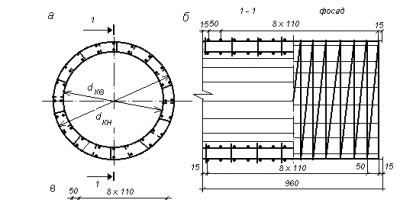
Reinforcement cage of round links consists of two rows (external and internal) of working spiral reinforcement, transverse reinforcement - clamps, as well as distribution longitudinal reinforcement (Fig. 7.6).

Rice. 7.6. Diagram of the reinforcing cage of a round pipe for a link 1 m long: A– cross section; b– view 1-1 and facade; V– spiral; d k– frame diameter; d H k , d B k– diameter of the location of the outer and inner spirals
The reinforcement cage consists of the same number of spirals located along the outer and inner contours of the link, which is determined by calculation. The Lengiprotransmost Design Institute has developed the following standard designs for reinforced concrete round pipes:
№GS 3.501.1-144– round reinforced concrete culverts for railways and roads;
№GS 3.501.1-144. Issue 0-1. Inv. No. 1313/2– round reinforced concrete culverts with flat support for railways in normal climatic conditions.
Z
Rice. 7.7. Reinforcement scheme for a round link with a flat base: A– cross section; b– view along the pipe axis; d kv ,
d book– diameters of internal and external frames
Links round pipes with flat base have more economical reinforcement, the diagram of which, according to the developments of Lengiprotransmost, is presented in Fig. 7.7.
Design of inlet and outlet heads reinforced concrete Round pipes are assumed to be the same from the unification conditions. The heads consist of slope walls (wings), located at an angle to the pipe axis, and portal walls (Fig. 7.8).
Reinforcement frame of slope wings made from meshes (Fig. 7.9).

Rice. 7.8. Round pipe head design: A– façade; b – section along the pipe axis; V - plan (embankment not shown); 1 – conical link; 2 – portal wall, 3 – slope wall; 4 – pattern block; 5 – foundation

Rice. 7.9. Design of the reinforcement frame of the slope wings of the round pipe head: A - facade; b – plan
The slope walls of the heads are installed on reinforced concrete slabs laid on crushed stone or gravel-sand preparation. A concrete tray is placed between the slope wings on a gravel-sand preparation (see Fig. 7.8).
WITH
Rice. 7.10. Diagram of a rectangular reinforced concrete pipe section: A– cross section; b– cut along the pipe axis
The standard design provides for an increase in elevated links by 0.5 m compared to normal ones. The following standard designs of prefabricated reinforced concrete pipes of rectangular cross-section have been developed:
№GS 3.501-177.93– reinforced concrete rectangular culverts for railways and roads (JSC Transmost, 1994);
№GS 3.501-177.93. Issue 0-2– rectangular pipes for railways in moderate and severe climatic conditions (JSC Transmost, 1994);
№GS 3.501-107. Inv. No. 1130/1.2– rectangular concrete culverts for railways and roads.
Reinforcement frame of a rectangular pipe link includes meshes consisting of working and distribution reinforcement, located along the external and internal contours, taking into account the provision of a protective layer of concrete, which are combined using clamps (Fig. 7.11).

Rice. 7.11. Reinforcement frame diagram of a rectangular link: A– cross section; b– view along the pipe axis
In the middle part of typical pipe structures, the length of the sections is 2.01 and 3.02 m. The links rest on the foundation along a layer of cement mortar. The foundations of the sections can be monolithic, prefabricated reinforced concrete or concrete blocks, shallow or deep. An expansion joint 3 cm thick is installed between the sections.
In reinforced concrete pipes of rectangular cross-section, they are used bell heads with sloped wings located at an angle of at least 20° (Fig. 7.12).
On railways built in areas with harsh climatic conditions, rectangular reinforced concrete and concrete culverts are most common. Currently, standard designs of rectangular pipes for harsh climatic conditions have been developed:
№GS 3.501.1-177.93. Issue 0–3. Pipes for railways and roads in particularly harsh climatic conditions. (JSC Transmost, 1994);
№GS 3.501-65. Inventory No. 1016. Culverts for railways and roads at a design temperature of minus 40 o C and below, deep seasonal freezing and ice dams. Rectangular concrete pipes. (Lengiprotransmost, 1976).

Rice. 7.12. Design of the outlet head of a rectangular pipe: A - facade; b – section along the pipe axis; V - plan (embankment not shown)
Links rectangular reinforced concrete pipes used with a hole from 1.5 to 6.0 m. They are based on prefabricated monolithic foundations, consisting of prefabricated reinforced concrete blocks of L- or T-shape (Fig. 7.13, 7.14) and monolithic concrete, as well as deep foundations on piles and pillars (Fig. 7.15, 7.16).

Rice. 7.13. Rectangular reinforced concrete pipe with L-shaped and T-shaped foundations: A - section cross section; b– head façade

Rice. 7.15. Rectangular reinforced concrete pipe with foundations on piles and pillars: A - head; b, c – cross section of sections

Rice. 7.16. General view of a rectangular reinforced concrete pipe with foundations on piles
Concrete rectangular pipe structures used with a hole from 1.5 to 6.0 m, which provide a water throughput capacity of up to 150 m 3 /s. The middle sections of the pipes are 3–4 m long. The structures of such pipes consist of reinforced concrete floor slabs, concrete wall blocks, nozzles, a tray and a foundation (Fig. 7.16, 7.17). Pipes with a hole of 1.5–3.0 m have solid foundations, and the rest are separate on a natural foundation, monolithic, prefabricated, and also deep laid on piles or pillars. The trays are concreted using sand preparation. The pipes have bell-shaped ends with increased inlet and normal outlet links.
Typical concrete culverts have similar foundations to reinforced concrete ones (Fig. 7.17, 7.18).

Rice. 7.17. Rectangular concrete pipes: a, b – cross section of section and head; V - with L-shaped and T-shaped foundations
In the typical design of rectangular culverts, foundations made of reinforced concrete blocks of L-shaped and T-shaped sections are provided for a freezing depth of the foundation soil equal to 2.3 and 4 m.
In harsh climatic conditions, in the presence of thawed and soft soils at the base, it is preferable to install the outer sections and head openings on pile foundations (see Fig. 7.16). The use of pile foundations increases the rigidity of the base and protects pipes from stretch marks. In case of weak foundation soils, it is advisable to use foundations with inclined piles in the outer sections and head openings.
When constructing culverts on permafrost soils, the natural regime of the foundation is maintained without disturbing natural conditions. In this case, preference is given to pipes with foundations on drilled columns with a diameter of 0.6–0.8 m (see Fig. 7.15, V).

Rice. 7.19. Design of the head of a concrete pipe with an ovoid cross-section: A - cross section; b– façade; 1 – opener section; 2 - general form
Structures of concrete and reinforced concrete pipes ovoid section used with a hole from 1.0 to 3.0 m (Fig. 7.19, 7.20). Reinforced concrete links of ovoidal pipes have reinforcement in the form of closed spirals (Fig. 7.21).This type of reinforcement cage ensures reliable operation of the structure taking into account the full range of loads. All sections of ovoidal pipe links operate as eccentrically compressed elements.
The use of concrete ovoidal pipes makes it possible to reduce the labor intensity of factory production and the consumption of reinforcing steel. They are used for embankment heights of up to 20 m.
Reinforced concrete pipes with an ovoid cross-section are more efficient structures when compared with round structures in terms of reinforcement consumption on average up to 40–45%.
During operation, compressive and tensile forces are observed in a monolithic foundation slab. If concrete easily copes with the former on its own, then to compensate for the stretching it is necessary to use reinforcement. This structural material increases the tensile strength of the slab base by 10 times. Moreover, the rods must be knitted correctly, in accordance with the standards, according to the reinforcement scheme, the mesh must be laid in two layers with a minimum vertical distance of 10 cm, a protective layer of 3 cm.
The basic requirements for a monolithic slab are given in. They indicate how to correctly position and knit reinforcing mesh, and what supports to use to provide the bottom protective layer. The use of rods with flaking rust is not allowed.
The periodic cross-section rods provide high adhesion, and the binding wire is more reliable than plastic clamps. However, reinforcement should begin in stages: choosing a rational scheme, calculating the cross-section of the rods, fixing the frames in space using special elements.
Reinforcement schemes
Due to the complexity of calculations and the small dimensions of buildings in low-rise construction, a simplified scheme is recommended. Two grids at a distance of 10 cm vertically with at least identical cells. If the developer wants to save on pouring the slab, the calculation should be ordered from specialists who will calculate the minimum required reinforcement, use thin reinforcement in the center of the foundation, strengthen the perimeter, and the places where the internal walls pass.
If the foundation dimensions are more than 3 m on any side of the slab, it is recommended to use rods of at least 12 mm. To determine the minimum possible cross-section, the following method is used:
- calculation of the slab cross-section - length multiplied by thickness (for example, 6 m x 0.3 m);
- calculation of the minimum allowable cross-sectional area of the rod - the previous figure is divided by the minimum percentage of reinforcement (0.3% for concrete B20, 0.15% for grade B22.5, 0.1% for grade B15), for this example 1.8 m²/0 .15 = 27 cm²;
- calculation of the reinforcement area in each row - the result obtained is divided in half (in the example 27/2 = 13.5 cm²);
- determination of the minimum permissible cross-section of a rod depending on the mesh pitch (13.5 cm² / 31 rods every 20 cm for a slab 6 m long = 0.42 cm²;
Advice! If you need contractors, there is a very convenient service for selecting them. Just send in the form below a detailed description of the work that needs to be performed and you will receive proposals with prices from construction teams and companies by email. You can see reviews about each of them and photographs with examples of work. It's FREE and there's no obligation.
During the construction of pipelines, the reinforced concrete head performs several important functions. It ensures uniform movement of fluid through the pipeline due to uniform inclination, supports slopes and protects gaps from falling asleep with soil.
You can purchase reinforced concrete pipe heads from our company in a wide range. We offer several size options and guarantee excellent quality. The culvert head helps to increase the durability of pipelines and ensures their long-term trouble-free operation. We offer reinforced concrete products that have a number of advantages:
- High strength. It allows the product to withstand heavy mechanical loads.
- Resistance to temperature changes and minimal water absorption. These factors will allow you to withstand destructive environmental factors for a long time.
- Any reinforced concrete head undergoes multi-stage control, so we guarantee the absence of defects and maximum reliability.
The price of a reinforced concrete head of any size will be favorable, you can get the necessary information by calling us. We offer to place an order with delivery of products to the regions, please contact us!
We offer to buy OG heads
When constructing culverts, reinforced concrete flue caps are indispensable products. They are classified as reinforced concrete products for reclamation purposes, since they are designed to protect the road from atmospheric phenomena affecting it. Reinforced concrete OG heads are L-shaped elements that can be of different sizes.
Exhaust pipe caps are a necessary element to strengthen the roadside and prevent destruction. Our reinforced concrete plant offers high-quality exhaust caps made of heavy concrete, which has excellent strength characteristics.
We provide delivery to any region of the Russian Federation. We fulfill our delivery obligations regardless of the size of the shipment and the number of commodity items, the destination and the state of the transport network in the addressee’s region.
Prom ZhBI sends tens of tons of reinforced concrete products every day to different parts of the country. Our regular customers are large contracting organizations from Kaliningrad and Vladivostok, Arkhangelsk and Belgorod, Nizhny Novgorod and Astrakhan. The consistency of orders placed by construction companies and operating organizations at Prom-ZhBI is due to:
- our compliance with delivery conditions (deadlines, nomenclature and quantity of concrete products)
- efficiency in order processing
- compliance with the rules for transporting reinforced concrete products
- vast experience in organizing the transportation of reinforced concrete products, which allows you to avoid force majeure along the way
- well-functioning logistics system (we choose the most convenient and inexpensive delivery options)
With us you will always receive your ordered materials on time. We organize delivery of any goods manufactured in our production.
The low price for the entire range of products manufactured by the company is complemented by affordable delivery costs. At the same time, the Prom-ZhBI company takes upon itself all organizational efforts. We control:
- order completion and shipment
- route and travel time
- delivery time to the destination and order completeness at the unloading point
Regardless of the region in which you are located, delivery is organized as quickly as possible: no matter where you expect the cargo, it will arrive to you on time and without any effort on your part.
CENTRAL INSTITUTE REGULATORY
RESEARCH AND SCIENTIFIC AND TECHNICAL
INFORMATION"ORGTRANSSTROY"
MINISTRY OF TRANSPORT CONSTRUCTION
TEAM DEVICE
REINFORCED CONCRETE CULVER
DIAMETER 1 m UNDER THE ROAD
I. SCOPE OF APPLICATION
The technological map was developed taking into account progressive methods of organizing construction and production of work, as well as methods of scientific organization of labor and is intended for use in developing a project for the production of work and the organization of work and labor at the site.
The technological map provides for the construction of a single-point prefabricated reinforced concrete pipe with a diameter of 1 m, length 26.28 m under a highway (with an embankment height of 4 to 7 m).
The design of the pipe was adopted according to the “Standard design (501 Ж-5) of prefabricated unified concrete culverts for railways and roads” of Glavtransproekt, approved by order of the Ministry of Railways and the Ministry of Transport of July 8, 1966 No., inv. No. 101/1.
The pipe is mounted from prefabricated reinforced concrete elements:
the foundation is made of patterned blocks laid over crushed stone preparation;
pipe body - from links 1 long m;
heads with openers - from separate blocks.
Strengthening the riverbed at the heads is not provided for in the technological map.
In all cases of using a technological map, it is necessary to link it to local conditions of work.
II. INSTRUCTIONS FOR PRODUCTION PROCESS TECHNOLOGY
The pipe construction work includes:
preparation of the construction site;
marking works;
reception and placement of equipment, materials and structures at the construction site;
construction of a pit for the foundation of pipes and heads;
crushed stone preparation device;
installation of foundation blocks, pipe heads and links;
filling the cavity of the pit with soil;
concreting trays within the caps;
waterproofing works;
backfilling the pipe with soil.
Construction site preparation
A site in the pipe construction zone (at a distance of at least 10 m in each direction from the pipe axis) are planned with a bulldozer, giving slopes to ensure water drainage from the pipe.
At the exit head the natural channel is cleared, and at the entrance head at a distance of at least 1.5 m from the contour of the pit, they block the channel with soil and arrange a bypass ditch or embankment of the construction site. These measures must ensure complete drainage of surface water from the pit.
For the delivery of equipment, concrete blocks and materials, access roads are cleared and planned with a bulldozer, ensuring free passage along the ring traffic pattern.
Marking work
The position of the pipe is determined by the road design. The design organization must fix in kind and hand over to the work contractor the point of intersection of the road axis with the longitudinal axis of the pipe, the longitudinal axis of the pipe, secured with four outrigger stakes (Fig.), as well as a high-altitude benchmark.
By taking measurements along the axis of the pipe, the outline of the pit is outlined and marked with pegs.
At a distance of 1 m from the boundaries of the pit, they arrange a cast-off of boards or beams (Fig.) and mark on it the longitudinal axis of the pipe and the position of the heads, openings, and foundation sections.
If possible, the cast-off should be buried in the ground to protect it from damage by a bulldozer or excavator.

Sequence of installation of blocks and pipe sections
|
Crane parking |
Mounting number |
Element Marne (Block No.) |
Block weight, T |
Maximum boom reach, m |
|
|
Installation of output head blocks (portal and openings) |
|||||
|
Device for gravel and sand preparation for the outlet head |
|||||
|
Laying a patterned foundation block |
|||||
|
Installation of conical link and pipe links |
|||||
|
Laying patterned foundation blocks |
|||||
|
Installation of pipe sections |
|||||
|
Laying pattern blocks |
|||||
|
Installation of pipe sections |
|||||
|
Installation of inlet head blocks |
|||||
|
Device for gravel and sand preparation under the entrance head |
|||||
|
Installation of patterned foundation blocks |
|||||
|
Installation of pipe links and conical link |
|||||
Installers 4 grades - 1st and 3rd grade. - 1 take blocks and links and install them using guy ropes and crowbars in the design position.
Installer 3 raz. inspects and cleans blocks and links, slings them for feeding into the pit. Installer 2 jobs fills the vertical seams of the patterned foundation blocks with sand-cement mortar before installing the links. After installing and unfastening the head blocks, the entire team carries out work to fill the space behind the portal block and the base for the trays with a gravel-sand mixture.
Before installing the last links of the pipe, the installer 2 r. proceeds to pour cement mortar under the pipe links using a flat funnel (see. rice.). He finishes the work immediately after installing the last links of the pipe. Then he moves on to another pipe.
The insulator workers, working two at a time on each head, concrete the trays at the outlet and inlet heads. The concrete mixture is delivered by dump trucks and unloaded onto sand and gravel preparation, spread with shovels in an even layer and compacted with a surface vibrator. The surface of freshly laid concrete is smoothed with trowels and covered with sand. Immediately after installing the trays, the working units fall asleep simultaneously on both sides of the pit cavity. The soil is pushed with a D-271 bulldozer, tossed manually in hard-to-reach places, and then distributed with shovels in an even layer in the axles of the pit and compacted with electric rammers S-690. The insulator team also carries out work on sealing seams between the links and head blocks, arranging lining and coating waterproofing of the pipe, as well as backfilling the pipe with soil to a height of 0.5 m.
Two waterproofers 3 and 2 grades. They make bundles of tow, dip them in bitumen and caulk the seams between the links. Then they begin caulking the seams from the inside with cement mortar and jointing the joints. They work from the middle of the pipe to the edges, installing light portable circles under the top of each seam (see Fig.), supporting the solution in the seam.
Following them are two waterproofers of 4 and 2 grades. arrange adhesive insulation of seams. To do this, one cuts panels of bituminized fabric into strips 25 wide cm, at this time, another worker brings the mastic, pours hot bitumen mastic onto the joint with a thin stream from a scoop with a drain device, and both stick the bituminized fabric.
The same link arranges coating insulation using a spray unit or asphalt distributor.
The entire unit fills the pipe with soil using an E-302 excavator equipped with a grab. Workers compact the soil layer by layer using S-690 electric rammers.
Machine operators are obliged at the beginning of a shift (or at the beginning of work with a small volume of work) to check the readiness of machines for work, eliminate minor faults, fill the machine with fuel and water, operate the machine during work, and at the end of the shift (or work) clean the machine and report mechanic about any deficiencies noticed. The crane operator must check and test the rigging and installation equipment before starting work.
V. CALCULATION OF LABOR COSTS FOR THE CONSTRUCTION OF A PRECASTIC CULVER WITH 1 m HOLE, 26.28 m LONG
|
Code of norms and prices |
Description of work |
Squad composition |
Unit |
Scope of work |
Standard time, person-hour |
Price, rub.-kop. |
Standard time for the full scope of work, person-hours |
Cost of labor costs for the full scope of work, rubles-kopecks. |
|
|
A. Preparatory work |
|||||||||
|
EniR, 2-1-24, No. 6a |
Laying out a construction site with a bulldozer in 3 passes along one track |
Machinist 5 grades - 1 |
100m 2 |
||||||
|
Time-based |
Layout of a structure with axle extension and outrigger device |
2 sizes - 1 |
man-hour |
||||||
|
Reception of tools, fixtures and equipment and their installation, installation of lighting for the construction site |
Structural installers: 3 grades. - 1 1 size - 1 |
man-hour |
|||||||
|
EniR, 4-4-92, No. 1 |
Unloading and sorting of head blocks |
Crane operator 6 raz. - 1 Structural installers: 4 grades. - 1 3 size - 1 |
|||||||
|
EniR, 4-4-92, No. 3 |
Unloading and sorting pattern blocks |
||||||||
|
EniR, 4-4-92, No. 6 |
Unloading and sorting of pipe sections |
Crane operator 6 raz. - 1 Structural installers: 4 grades. - 1 3 size - 1 |
|||||||
|
Total |
|||||||||
|
B. Earthworks a) Digging a pit |
|||||||||
|
EniR, 2-1-15, table. 2, No. 56+d |
Development of group II soil with a bulldozer D-271 (when moving it up to 20 m) |
Machinist 5 grades - 1 |
100m 3 |
||||||
|
EniR, 2-1-10A, tab. 3, No. 3z |
Development of group II soil using an E-302 excavator |
Machinist 4 grades - 1 |
100m 3 |
||||||
|
EniR, 2-1-15, table. 2, No. 56+d, approx. 3, K = 0.85 |
Moving group II soil with a D-271 bulldozer at a distance of 20 m |
Machinist 5 grades - 1 |
100m 3 |
||||||
|
EniR, 2-1-31, table. 2, No. 1e, approx. 3a, K = 1.2 |
Refinement of group II soil in a pit manually after its development with an excavator and bulldozer |
Excavator 2 sizes. - 1 |
|||||||
|
EniR, 2-1-46, No. 26, K = 1.2 according to 2-1-31, approx. 3b |
Cleaning the bottom of a pit in group II soils manually with cutting off irregularities, filling in depressions with soil compaction, checking the planned surface using a template |
Excavator 2 sizes. - 1 |
100m 2 |
||||||
|
b) Backfilling of pit and pipe cavities |
|||||||||
|
EniR, 2-1-15, table. 2, No. 56+d, approx. 3, K = 0.85 |
Moving group II soil with a D-271 bulldozer at a distance of 20 m |
Machinist 5 grades - 1 |
100 m 3 |
||||||
|
EniR, 2-1-44, table. 1, No. 26 |
Filling the pit sinuses with soil manually with compaction |
Diggers: 2 grades. - 1 1 size - 1 |
|||||||
|
In relation to EniR, 2-1-45, table. 3, No. 2a, K = 1.2 |
Compaction of group II soil with electric rammers after backfilling in layers of 15 cm |
Excavator 3 sizes. - 1 |
100m 2 |
||||||
|
EniR, 2-1-12, table. 3, No. 1v |
Backfilling the pipe with soil to a height of 0.5 m excavator E-302 equipped with a grab bucket |
Excavator operator 5 raz. - 1 |
100m 3 |
||||||
|
In relation to EniR, 2-1-45, table. 3, No. 1a, K = 1.2 |
Compaction of soil with electric rammers when backfilling pipes in layers 20 thick cm (66m 3 : 0,2m = 330m 2) |
Excavator 3 sizes. - 1 |
100m 2 |
||||||
|
Total |
|||||||||
|
Total for earthworks |
|||||||||
|
B. Construction of two heads |
|||||||||
|
EniR, 4-4-88, No. 56 |
Device for gravel and sand preparation for bevels and head trays in layers of 15 cm (11,8: 0,15 = 79m 2) |
3 size - 1 2 sizes - 1 |
100m 2 |
||||||
|
EniR, 4-4-88, No. 4A |
Crushed stone preparation device with a thickness of 0.1 m(1,2: 0,1 = 12m 2) |
100m 2 |
|||||||
|
EniR, 4-4-91, table. 2, No. 1b |
Installation of pattern blocks No. 24 weighing 1.5 tons by crane |
Crane operator 6 raz. - 1 Structural installers: 4 grades. - 1 3 size - 2 |
|||||||
|
EniR, 4-4-94, No. 2b |
Installation by crane of conical links No. 27 weighing 1.3 tons |
Crane operator 6 raz. - 1 3 size - 2 |
|||||||
|
EniR, 4-4-93, No. 1 |
Installation of a portal wall weighing 3 tons by crane block No. 35 |
Crane operator 6 raz. - 1 Structural installers: 4 grades. - 2 3 size - 2 |
|||||||
|
EniR, 4-4-93, No. 5 |
Installation by crane of blocks No. 39p, l of slope wings weighing 3.1 t |
||||||||
|
EniR, 4-4-99, No. 1 |
Caulk the seams of links with portal walls with tow impregnated with bitumen |
Structural installers: 4 grades. - 1 3 size - 1 |
1m seam |
||||||
|
EniR, 4-4-99, No. 3 |
Joint insulation device |
3 size - 1 |
|||||||
|
EniR, 4-4-99, No. 2 |
Sealing the seams between the conical link and the portal wall of the head with cement mortar |
Structural installers: 4 grades. - 1 |
1m seam |
||||||
|
EniR, 4-4-97, No. 2 |
Caulking of vertical seams between the blocks of the portal wall and the slope wings of the head |
1m seam |
|||||||
|
EniR, 4-4-97, No. 4 |
Filling vertical joints between head blocks with cement mortar |
Structural installers: 4 jobs - 1 3 size - 1 |
1m seam |
||||||
|
EniR, 4-4-97, No. 7 |
Joining the seams between the head blocks |
Structural installers: 4 grades. - 1 3 size - 1 |
1m seam |
||||||
|
EniR, 4-4-101, No. 1 |
Coating insulation device |
Waterproofers: 3 sizes. - 2 |
|||||||
|
Total for 2 heads |
|||||||||
|
D. Installation of links and pipes and construction of foundations |
|||||||||
|
a) Section 2.01 m long |
|||||||||
|
EniR, 4-4-88, No. 4a |
Crushed stone preparation device with a layer thickness of 0.1 m |
Road workers: 4 grades. - 1 3 size - 1 2 sizes - 1 |
|||||||
|
EniR, 4-4-91, No. 1b, table. 2 |
Laying the foundation of a pipe body weighing 1.9 tons with a crane of pattern block No. 4 |
Crane operator 6 raz. - 1 Structural installers: 4 grades. - 1 3 size - 2 |
|||||||
|
EniR, 4-4-94, No. 2b |
Installation of 1.1 t pipe sections by crane |
Crane operator 6 raz. - 1 Structural installers: 4 grades. - 2 3 size - 2 |
|||||||
|
EniR, 4-4-99 No. 1 |
Structural installers: 4 grades. - 1 3 size - 1 |
1m seam |
|||||||
|
EniR, 4-4-99, No. 3 |
Installation of adhesive joint insulation |
Waterproofers: 4 sizes. - 1 3 size - 1 |
1m seam |
||||||
|
EniR, 4-4-101, No. 1 |
|||||||||
|
EniR, 4-4-99, No. 2 |
1m seam |
||||||||
|
Total per section |
|||||||||
|
Total for 2 sections |
|||||||||
|
b) Section 3.02 m long |
|||||||||
|
EniR, 4-4-88, No. 4a |
Crushed stone preparation device with a layer thickness of 0.1 m |
Road workers: 4 grades. - 1 3 size - 1 2 sizes - 1 |
|||||||
|
EniR, 4-4-91, table. 2, No. 16 |
Laying the foundation of a pipe body weighing 1.4 with a crane of pattern block No. 5 T |
Crane operator 6 raz. - 1 Structural installers: 4 grades. - 1 3 size - 2 |
|||||||
|
EniR, 4-4-94, No. 26 |
Laying pipe sections weighing 1.1 by crane T |
Crane operator 6 raz. - 1 Structural installers: 4 grades. - 2 3 size - 2 |
|||||||
|
EniR, 4-4-99, No. 3 |
Installation of adhesive joint insulation |
Waterproofers: 4 sizes. - 1 3 size - 1 |
1m seam |
||||||
|
EniR, 4-4-99, No. 1 |
Caulking the seams of pipe links with tow impregnated with bitumen |
Structural installers: 4 grades. - 1 3 size - 1 |
1m seam |
||||||
|
EniR, 4-4-101, No. 1 |
Coating waterproofing device |
Waterproofers 3 sizes. - 2 |
|||||||
|
EniR, 4-4-99, No. 2 |
Sealing joints with cement mortar |
Installer of structures 4 grades. - 1 |
1m seam |
||||||
|
Total |
|||||||||
|
Total for 5 sections |
|||||||||
|
A total of 7 pipe sections |
|||||||||
|
D. Arrangement of trays at the heads |
|||||||||
|
EniR, 4-4-98 |
Concreting of trays at the inlet and outlet heads with a thickness of 20 cm |
Concrete workers: 4 grades. - 1 3 size - 2 |
|||||||
|
EniR, 17-31, No. 1 + 3 |
Caring for freshly laid concrete |
Road worker 1 grade - 1 |
100m 2 |
||||||
|
Total |
|||||||||
|
Total per pipe |
|||||||||
|
Including: for the work of unit No. 1 (I cycle) №№ 1 - 10, 17; 29; 36 |
|||||||||
|
Tapered links No. 27 |
|||||||||
|
Round links No. 13 |
|||||||||
|
Portal wall blocks No. 35 |
|||||||||
|
Blocks of slope walls No. 39l and No. 39p |
|||||||||
|
Concrete mix M-150 |
|||||||||
|
Cement mortar M-150 |
Excavator equipped with backhoe and grab |
||||||||
|
Bulldozer |
|||||||||
|
Mobile power station |
|||||||||
|
Mobile spray unit |
|||||||||
|
Surface vibrator |
|||||||||
|
Electric rammers |
|||||||||
|
Digging shovels LKO-1 |
|||||||||
|
Picking shovels LP-1 |
|||||||||
|
Carpenter's axes |
|||||||||
|
Portable circles |
|||||||||
|
Cross saw |
|||||||||
|
Level 1 long m |
|||||||||
|
Roulette RS-20 |
|||||||||
|
Steel screws |
TsNIIS Ministry of Transport |
||||||||
|
Flat funnels |
|||||||||
|
Steel caulking |
|||||||||
|
Water container |
|||||||||
|
Container for bitumen varnish |
|||||||||
|
Level slats |
|||||||||
|
Trowels (trowels) |
|||||||||