The ability to solder in modern life, saturated with electrical appliances and electronics, is just as necessary as the ability to use a screwdriver and a plunger. There are many methods for soldering metals, but first of all you need to know how to solder with a soldering iron, although other methods are feasible and may also be needed at home. This article is intended to help those who want to master the technology of manual soldering work.
Fluxes
Soldering fluxes are divided into neutral (inactive, acid-free), which do not react chemically with the base metal or interact to an insignificant extent, activated, which chemically act on the base metal when heated, and active (acidic), which act on it even when cold. In regard to fluxes, our century has brought the most innovations; mostly still good, but let's start with the unpleasant ones.
First, technically pure acetone for washing rations is no longer widely available due to the fact that it is used in the underground production of drugs and itself has a narcotic effect. Substitutes for technical acetone are solvents 646 and 647.
Secondly, zinc chloride in activated flux pastes is often replaced with sodium teraborate - borax. Hydrochloric acid is a highly toxic, chemically aggressive volatile substance; Zinc chloride is also toxic, and when heated it sublimates, i.e. evaporates without melting. Borax is safe, but when heated it releases a large amount of water of crystallization, which slightly impairs the quality of soldering.
Note: borax itself is a soldering flux for soldering by immersion in molten solder, see below.
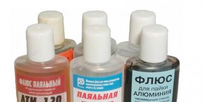
The good news is that there is now a wide range of fluxes on sale for all soldering occasions. For ordinary soldering work, you will need (see figure) inexpensive SCF (alcohol rosin, former CE, second in the list of acid-free fluxes in Table I.10 in the figure above) and soldering (etched) acid, this is the first acid flux on the list. SKF is suitable for soldering copper and its alloys, and soldering acid is suitable for steel.
SKF rations must be washed: rosin contains succinic acid, which destroys the metal with prolonged contact. In addition, accidentally spilled SCF instantly spreads over a large area and turns into an extremely sticky muck that takes a very long time to dry, the stains from which cannot be removed from clothes, furniture, or the floor and walls. In general, SKF is a good flux for soldering, but not for slow-witted people.
A complete substitute for SCF, but not so nasty if handled carelessly, is TAGS flux. Steel parts are more massive than is permissible for soldering with soldering acid, and more durable, they are soldered with F38 flux. The universal flux can be used to solder almost any metal in any combination, incl. aluminum, but the strength of the joint with it is not standardized. We'll come back to soldering aluminum later.
Note: Radio amateurs, keep in mind - there are now fluxes on sale for soldering enameled wires without stripping!
Other types of soldering
Hobbyists also often solder with a dry soldering iron with a bronze untinned tip, the so-called. soldering pencil, pos. 1 in Fig. It is good where solder spreading outside the soldering zone is unacceptable: in jewelry, stained glass, soldered objects of applied art. Sometimes surface-mounted microchips are also dry-soldered with pin spacing of 1.25 or 0.625 mm, but this is a risky business even for experienced specialists: poor thermal contact requires excessive soldering iron power and prolonged heating, and it is impossible to ensure stable heating during manual soldering. For dry soldering, use harpius from POSK-40, 45 or 50 and flux pastes that do not require removal of residues.
Dead-end twists of thick wires (see above) are soldered by immersion in a futorka - a bath of molten solder. Once upon a time, the futorka was heated with a blowtorch (pos. 2a), but now this is primitive savagery: an electrofutorka, or soldering bath (pos. 2) is cheaper, safer and gives better soldering quality. The twist is introduced into the futor through a layer of boiling flux, which is applied to the solder after it has melted and warmed up to operating temperature. The simplest flux in this case is rosin powder, but it soon boils away and burns even faster. It is better to flux the futor with brown, and if a soldering bath is used for galvanizing small parts, then this is the only possible option. In this case, the maximum temperature of the futor should not be lower than 500 degrees Celsius, because zinc melts at 440.
Finally, solid copper in products, e.g. pipes are soldered using high-temperature flame soldering. It always contains unburned particles that greedily absorb oxygen, so the flame has, as chemists say, restorative properties: it removes residual oxide and prevents the formation of new ones. At pos. 3 you can see how the flame of a special soldering torch literally blows out everything unnecessary from the soldering area.
High-temperature soldering is carried out, see Fig. on the right, evenly rubbing the soldering area with pressure with a stick of hard solder 2. The flame of the torch 3 should follow the solder so that the hot spot is not exposed to air. First, the soldering zone is heated until the colors become tarnished. You can solder something else to the surface tinned with hard solder using soft solder as usual. For more information on flame soldering, see later when it comes to pipes.
It’s funny, but in some sources the soldering torch is called a soldering station. Well, a rewrite is a rewrite, whatever you get from it. In fact, a desktop soldering station (see next figure) is equipment for fine soldering work: with microchips, etc., where overheating, spreading of solder where it is not needed, and other flaws are unacceptable. The soldering station accurately maintains the set temperature in the soldering zone, and, if the station is gas, it controls the gas supply there. In this case, the torch is included in its kit, but the soldering torch itself, the soldering station, is nothing more than a quarry - St. Basil's Cathedral.
How to solder aluminum
Thanks to modern fluxes, soldering aluminum has become generally no more difficult than copper. F-61A flux is intended for low-temperature soldering, see fig. Solder – any analogue of Avia solders; There are different ones on sale. The only thing is that it is better to insert a tinned bronze rod into the soldering iron with notches on the tip approximately like a file. Under the layer of flux, it will easily scrape off the strong oxide film, which prevents aluminum from being soldered just like that.
F-34A flux is intended for high-temperature soldering of aluminum with 34A solder. However, you need to be very careful when heating the soldering zone with a flame: the melting point of aluminum itself is only 660 Celsius. Therefore, for high-temperature soldering of aluminum it is better to use flameless chamber soldering (furnace-heated soldering), but the equipment for it is expensive.
There is also a “pioneer” method of soldering aluminum with preliminary copper plating. It is suitable when only electrical contact is required and mechanical stress in the soldering area is excluded, for example, if it is necessary to connect an aluminum casing to the common busbar of a printed circuit board. “In a pioneering way,” aluminum soldering is carried out on the installation shown in Fig. left. Copper sulfate powder is poured in a heap into the soldering zone. A harder toothbrush, wrapped in bare copper wire, is dipped into distilled water and the vitriol is rubbed with pressure. When a copper spot appears on the aluminum, it is tinned and soldered as usual.
Fine soldering
Soldering printed circuit boards has its own peculiarities. How to solder parts onto printed circuit boards, in general, see the small master class in the drawings. Tinning of wires is no longer necessary, because the terminals of the radio components and chips are already tinned.
In amateur conditions, firstly, there is little point in tinning all current-carrying paths if the device operates at frequencies up to 40-50 MHz. In industrial production, boards are tinned using low-temperature methods, for example. spraying or galvanic. Heating the tracks along their entire length with a soldering iron will worsen their adhesion to the base and increase the likelihood of delamination. After installing the component, it is better to varnish the board. This will immediately darken the copper, but this will not affect the performance of the device in any way, unless we are talking about microwaves.
Then, look at the ugly thing on the left of the trail. rice. For such a marriage, and in the bad memory of the Soviet MEP (Ministry of Electronic Industry), installers were demoted to loaders or helpers. It’s not even a matter of appearance or excessive consumption of expensive solder, but, firstly, the fact that during the cooling of these plaques both the mounting pads and the parts overheated. And large heavy influxes of solder are rather inert weights for already weakened tracks. Radio amateurs are well aware of the effect: if you accidentally push a “cuttlefish” board onto the floor, 1-2 or more tracks peel off. Without waiting for the first re-soldering.
Solder beads on printed circuit boards must be round and smooth with a height of no more than 0.7 times the diameter of the mounting pad, see on the right in Fig. The tips of the leads should protrude slightly from the beads. By the way, the board is completely homemade. There is a way at home to make a printed edit as accurate and clear as a factory one, and even display the inscriptions you want. White spots are reflections from the varnish during photography.
Swellings that are concave and especially wrinkled are also a defect. Just a concave bead means that there is not enough solder, and a wrinkled bead means that air has penetrated into the solder. If the assembled device does not work and there is a suspicion of a faulty connection, look first in these places.
ICs and chips
In essence, an integrated circuit (IC) and a chip are the same thing, but for clarity, as is generally accepted in technology, we will leave the “microchip” microcircuits in DIP packages, up to and including large ones in terms of the degree of integration, with pins separated by 2.5 mm, installed in mounting holes or soldering pins if the board is multilayer. Let the chips be ultra-large “million-dollar” ICs, mounted on the surface, with pin pitches of 1.25 mm or less, and the microchips – miniature ICs in the same cases for phones, tablets, and laptops. We do not touch processors and other “stones” with rigid multi-row pins: they are not soldered, but installed in special sockets, which are sealed into the board once when it is assembled at the enterprise.
Soldering iron grounding
Modern CMOS (CMOS) ICs are the same in sensitivity to static electricity as TTL and TTLSh, holding a potential of 150 V for 100 ms without damage. The amplitude value of the effective network voltage is 220 V - 310 V (220x1.414). Hence the conclusion: you need a low-voltage soldering iron, for a voltage of 12-42V, connected through a step-down transformer on the hardware, not through a pulse generator or capacitive ballast! Then even a direct test on the tip will not ruin expensive chips.
There are still random, and even more dangerous, surges in mains voltage: welding was turned on nearby, there was a power surge, the wiring sparked, etc. The most reliable way to protect yourself from them is not to remove “stray” potentials from the soldering iron tip, but not to let them escape from there. For this purpose, even at special enterprises of the USSR, the circuit for switching on soldering irons was used, shown in the figure:
The connection point C1-C2 and the transformer core are connected directly to the protective grounding loop, and the screen winding (an open turn of copper foil) and the grounding conductors of the workplaces are connected to the middle point of the secondary winding. This point is connected to the circuit with a separate wire. If the transformer has sufficient power, you can connect as many soldering irons as you like to it, without worrying about grounding each one individually. At home, points a and b are connected to a common ground terminal with separate wires.
Microcircuits, soldering
Microcircuits in DIP packages are soldered like other electronic components. Soldering iron – up to 25 W. Solder – POS-61; flux - TAGS or alcohol rosin. You need to wash off its remains with acetone or its substitutes: alcohol takes the rosin hard, and it is not possible to completely wash it off between the legs either with a brush or a rag.
As for chips, and especially microchips, soldering them manually is strongly not recommended for specialists of any level: this is a lottery with very problematic winnings and very likely losses. If it comes to such subtleties as repairing phones and tablets, you will have to fork out for a soldering station. Using it is not much more difficult than a hand soldering iron, see the video below, and the prices of quite decent soldering stations are now affordable.
Video: microcircuit soldering lessons
Microcircuits, desoldering
“Correctly”, ICs are not desoldered for testing during repairs. They are diagnosed on site using special testers and methods, and the unusable ones are removed once and for all. But amateurs cannot always afford it, so just in case, below we provide a video about methods for desoldering ICs in DIP packages. Craftsmen also manage to desolder chips with microchips, for example, by slipping a nichrome wire under a number of pins and heating them with dry soldering irons, but this is an even less winning lottery than manual installation of large and extra-large ICs.
Video: desoldering microcircuits - 3 methods
How to solder pipes
Copper pipes are soldered using a high-temperature method with any hard copper solder with activated flux paste, which does not require removal of residues. Next, there are 3 options:
- In copper (brass, bronze) couplings - soldering fittings.
- With full distribution.
- With incomplete distribution and compression.
Soldering copper pipes into fittings is more reliable than others, but requires significant additional costs for couplings. The only case when it is irreplaceable is a drainage device; then a tee fitting is used. Both soldered surfaces are not tinned in advance, but are coated with flux. Then the pipe is inserted into the fitting, securely fixed and the joint is soldered. Soldering is considered complete when the solder stops going into the gap between the pipe and the coupling (0.5-1 mm is needed) and protrudes outward as a small bead. The fastener is removed no earlier than 3-5 minutes after the solder has hardened, when the joint can already be held by hand, otherwise the solder will not gain strength and the joint will eventually leak.
How pipes with full distribution are soldered is shown on the left in Fig. The “distributed” soldering holds the same pressure as the fitting one, but requires additional pressure. special tools for unrolling the socket and increased solder consumption. Fixing the soldered pipe is not necessary; it can be pushed into the socket with a twist until it jams tightly, so soldering with full distribution is often done in places that are inconvenient for installing the clamp.
In home wiring made from thin-walled pipes of small diameter, where the pressure is already low and its losses are insignificant, soldering with incomplete expansion of one pipe and narrowing of the other may be advisable, pos. I on the right in Fig. To prepare the pipes, a round stick made of hard wood with a conical tip of 10-12 degrees on one side and a truncated-conical hole of 15-20 degrees on the other, pos. II, is sufficient. The ends of the pipes are processed until they fit into each other without jamming for approx. by 10-12 mm. The surfaces are tinned in advance, more flux is applied to the tinned ones and they are connected until they jam. Then they heat until the solder melts and prop up the narrowed pipe until it jams. Solder consumption is minimal.
The most important condition for the reliability of such a joint is that the narrowing must be oriented along the flow of water, pos. III. Bernoulli's school law is a generalization for an ideal fluid in a wide pipe, and for a real fluid in a narrow pipe, due to its (liquid) viscosity, the maximum pressure jump shifts opposite to the current, pos. IV. A component of pressure force arises, pressing the narrowed pipe against the distributor, and the soldering turns out to be very reliable.
What else?
Oh yes, soldering iron stands. The classic one, on the left in the figure, is suitable for any rod. Where the trays for solder and rosin should be placed on it is up to you; there are no regulations. For low-power soldering irons with an apron, simplified stands-brackets in the center are suitable.


Soldering is a method of creating a permanent connection by introducing into the contact zone a molten material with a melting point lower than that of the materials of the parts being joined. You can learn how to solder correctly with a soldering iron by mastering the technology in practice.
Purpose of the device
The electric soldering iron is available with a supply voltage from 12 to 220V. It is difficult to manufacture a low-power design for high voltage, since this requires many layers of thin wire, which leads to an increase in size. In addition, it is chosen based on work safety conditions.
It is convenient to select the power of the soldering iron using a simple table:

The optimal tip temperature is maintained manually or automatically. For this purpose, thyristor regulators are used.
To increase service life, the end of the soldering iron can be forged. In this case, copper will dissolve less in the solder. Before using a soldering iron, the tip is given a certain shape with a file. The most common are corner and cut. The end is given a knife-like shape in order to simultaneously solder several contacts of a microcircuit or connector pins.

Tools
Before properly soldering with a soldering iron, the work area should be equipped with the necessary tools:
- Stand. The heated device is located on the stand. It also serves to place flux and is a platform for working with wires. A “crocodile” with a piece of foam rubber is additionally attached to it for cleaning the sting.
- Tripod. It includes clamps (“crocodiles”) that can be moved in height and rotated, a tray with rosin, and a holder for a soldering iron.
- Set of tools. It is needed to support parts, give wires desired shapes, and clean solder surfaces. Such tools include tweezers, pliers, wire cutters, round nose pliers, files, a knife, and sandpaper.
Soldering secrets

How to use a soldering iron?
Foreign substances are removed from the surfaces of parts by sanding with sandpaper and degreasing with acetone or gasoline.
The tip is cleaned of oxides and soot with a file, block or sandpaper.
The soldering iron is heated, its end is coated with rosin, and then tinned. To do this, the solder on the tip is rubbed with a wooden block. The entire working surface should acquire a characteristic silver color.
The solder heats up. A small part of it in the form of a drop is applied to the joint and leveled. If necessary, it is added to the required amount until the contact area is covered. The connection area warms up. How to solder wires correctly? The contact of the tip with the conductor should be over the largest possible area, and not with the tip, as inexperienced installers do. In this case, the rosin must still remain on the drop of solder so that its oxidation does not begin. The soldering process is carried out in one step. If you pull the tip back and press it back into the part several times, the solder will turn gray due to oxidation as the rosin evaporates sooner. During the cooling process, the parts must remain motionless. When the wires are displaced when the solder has not yet hardened, microcracks form in it, worsening the strength of the connection and creating additional electrical resistance.
Remains of rosin are removed with a brush moistened with alcohol.
Soldering wires
Let's figure out how to properly solder wires with a soldering iron. First of all, their ends intended for connection are freed from insulation. It is important to warm up the wires being connected properly. To do this, the dimensions of the tip must correspond to the dimensions of the parts. If the soldering iron is too large, then adjacent elements will be damaged during operation. With its small size, soldering will be unreliable, since the parts are difficult to heat up.
Preparing the wire involves removing the insulation from its end. It is removed with a knife or wire cutters. The stranded wire should be twisted so that individual parts do not stick out, and tinned. To do this, it is lowered into a bath of rosin, a drop of solder is taken with a soldering iron and passed several times along the copper wires. During the tinning process, the wire must be heated and rotated so that it is coated on all sides. To prepare for further work, the tinned end is dipped into molten rosin and thus “varnished”. The excess can then be easily removed by hand.
Solder is a weak alloy and will break under light loads. The wires to be connected are pre-stripped and twisted. To do this, they must have a common axis. Their centers should be aligned, after which one wire is twisted along the length of the other. A similar operation is performed with the second end. A melt of rosin is applied to the joint, and then solder. The twist should be heated for 2-3 seconds.

If the quantity is insufficient, solder must be added so that the coating is uniform and shiny. Many people do not understand why the connection does not warm up even with a powerful device. How should soldering be done with a soldering iron in this case? The fact is that heat spreads from bottom to top. Therefore, the twist must be heated from below. When overheated, the solder spreads, and when there is not enough heat, the coating becomes loose.
Single-core wires are cleaned to a shine and dipped in rosin. Then they are connected and heated for 3-5 seconds. and apply solder. A heat-shrinkable tube of a larger diameter is put on the exposed wire, which shrinks with increased temperature, after which reliable insulation is formed. If the solder cools down quickly, use a lighter to heat it up. Having mastered how to solder wires correctly, you can begin more complex operations.
Twisting copper and aluminum wires together is unacceptable due to heat generation in the contact resistance. They are fixed through an intermediate element, which can be a bolted connection separated by washers, a terminal clamp, or a layer of other metal. Tin-based aluminum solder is also suitable for copper wire and can be a reliable intermediate layer for them.
Soldering radio components
Soldering with a radio element is carried out by twisting or overlapping, using a heat sink, for example, with tweezers. The heating of many parts of electrical circuits should not exceed 70 ºС for a duration of more than 3 seconds.
On a printed circuit board, the mounting area around the perimeter of the hole is covered with a layer of solder. Then the tinned and rosin-coated end of the conductor is inserted into it. It is heated and moistened with an added drop of solder. The tip should touch the pin and the board track at the same time. Excess solder is easily removed with copper braiding. The work is done efficiently when all soldering points are similar to each other. The leads of the radio elements are bent and inserted into the holes of the board. The ends on the reverse side are bent slightly so that the part does not fall out.
The soldering iron cannot be kept dry for a long time in a heated state. It becomes covered with a layer of oxides, and the tip will have to be cleaned and tinned again. There should always be a layer of molten rosin at the end, and the soldering iron should be turned off during long intervals between work. Also, old solder is periodically removed from it with a sponge.
Elements of boards of various equipment can fail under the influence of static electricity. To prevent its occurrence, the soldering iron body should be grounded.
Working with microcircuits
Let's look at how to properly solder microcircuits. The process has some peculiarities. Microcircuits cannot withstand overheating. There should be no excess solder at the joints. To do this, use a soldering iron for microcircuits with temperature control.
Simultaneous heating of the contacts is carried out using a hair dryer with nozzles. The area on the board needs to be cleaned. Acetone or universal varnish solvent is suitable for this. Then the hair dryer is turned on and its temperature is set at 330-370 ºС. At the minimum blowing speed, the chip heats up and is immediately removed with tweezers after the contacts have melted. Then the soldering area is lubricated with flux, and a new microcircuit is installed in place of the faulty one. When heated with a hairdryer, it sags a little due to the melting of the contacts, which is a signal that the operation is complete. The soldering area is wiped with acetone to remove any remaining flux. Sufficiently powerful contacts can be additionally heated with a soldering iron.
When simple ones are mastered, you can move on to complex compounds, for example, dissimilar metals using gas, furnace or pulse heating.

Soldering aluminum
Difficulties in soldering aluminum are associated with its low melting point (660 ºС) and strong oxide film. The parts are heated in an oven or with a gas flame burner. Their preparation consists of removing fats with a solvent and mechanical cleaning with sandpaper, an abrasive wheel or a stainless steel brush. In this case, the oxide film is formed again, but its thickness is much less than the previous one. Then flux is applied to the joint and heated to the melting temperature of the solder. The electrode rod is touched to the joint until it begins to melt.

Solder for soldering aluminum at temperatures of 150-400 ºС can be based on zinc, tin, cadmium (low-melting). It has poor corrosion resistance and requires additional coatings. Refractory solders, such as silumin (590-600 ºС), 34A (530-550 ºС) and others, are more reliable and are used more often. Aluminum alloys have a lower melting point. They are soldered with furnace heating, which is more precisely regulated.
Conclusion
How to properly solder wires and microcircuits with a soldering iron? The answer to this question implies, first of all, careful preparation of the tool and parts. During the process of creating a permanent connection, the layer of molten solder must always be protected with flux. For each operation, a soldering iron of appropriate power and the shape of the working surface of the tip is selected. When the parts are connected correctly and the temperature is maintained, the soldering is reliable and lasts a long time.
 How to solder correctly?
Before you start considering the question: “How to solder correctly?” One thing needs to be stated...
Soldering varies. You need to understand that there is a big difference in the method of soldering a hefty 2-watt resistor onto a regular printed circuit board and, for example, a BGA chip onto a multilayer cell phone board.
If in the first case you can get by with a simple 40-watt electric soldering iron, solid rosin and solder, then in the second case you will need to use devices such as a hot-air station, no-clean flux, solder paste, stencils and, possibly, a bottom heating station for the boards.
As you can see, the difference is significant.
In each specific case, you need to choose the soldering method that is most suitable for a specific type of installation. So, for soldering microcircuits in a planar package, it is better to use hot-air soldering, and for installing ordinary output resistors and large-sized electrolytic capacitors, it is worth using contact soldering with an electric soldering iron.
Let's look at the simplest rules of conventional contact soldering.
To begin with, it is enough for a novice radio amateur to master conventional contact soldering with the simplest and cheapest electric soldering iron with a copper tip.
First you need to prepare a minimum soldering kit and soldering tool. How to prepare an electric soldering iron for use has already been discussed in the article on preparing and caring for a soldering iron.
Many people believe that for soldering it is better to use a soldering iron with a non-burnable tip. Unlike a copper tip, a non-fading tip does not require periodic sharpening and tinning, since no depressions - cavities - are formed on its surface.

Burnt out soldering iron tip
(for clarity, the copper tip is pre-processed with a file).
The photo shows that the edge of the copper tip is uneven, and the resulting depressions are filled with frozen solder.
The non-burnable tip of widely used soldering irons, as a rule, has a cone-shaped shape. Such a tip is not wetted by molten solder, that is, it cannot be used to take solder onto the tip. When working with such a soldering iron, the solder is delivered to the soldering site using thin solder wire.
It is clear that using solder in pieces or rods when soldering with a soldering iron with a non-burnable tip is difficult and inconvenient. Therefore, for those who want to learn how to solder, it is better to start their practice with a regular electric soldering iron with a copper tip. The disadvantages of its use are easily compensated by such conveniences as the ease of using solders in any design (wire, rod, lump, etc.), the ability to change the shape of the copper tip.
An electric soldering iron with a copper tip is convenient because it can be used to easily measure the amount of solder that needs to be brought to the soldering site.
Cleanliness of soldered surfaces.
The first rule of high-quality soldering is the cleanliness of the surfaces being soldered. Even with new radio components purchased in a store, the terminals are covered with oxides and contaminants. But these minor contaminants, as a rule, are dealt with by flux, which is used during the soldering process. If it is clear that the terminals of radio components or copper conductors are heavily dirty or covered with oxide (greenish or dark gray), then before soldering they need to be cleaned either with a penknife or sandpaper.
This is especially true if used radio components are used when assembling an electronic device. A dark coating usually forms on their terminals. This is an oxide that will interfere with soldering.
Tinning.
Before soldering, the surface of the leads must be tinned - covered with a thin and even layer of solder. If you pay attention to the conclusions of new radio components, then in most cases you will notice that their conclusions and contacts are tinned. Soldering of tinned leads is faster and of better quality, since there is no need to pre-prepare the leads for soldering.
To tin a copper conductor, first remove the insulation from its surface and clean it of contaminants, if any. Then you need to treat the soldering surface with flux. If lump rosin is used as a flux, then the copper wire can be placed on a piece of rosin and touch the wire with a well-heated soldering iron tip. First, you need to take a little solder onto the soldering iron tip.
Next, moving along the wire, we distribute the molten solder over the surface of the conductor, trying to heat the conductor itself as best and evenly as possible. At the same time, the lump rosin melts and begins to evaporate under the influence of temperature. An even coating of tin-lead solder should form on the surface of the conductor without lumps or pellets.

Melted rosin helps reduce the surface tension of the molten solder and improves the wettability of the surfaces being soldered. Thanks to the flux (in this case, rosin), the conductor is uniformly coated with a thin layer of solder. Flux also helps remove contaminants and prevents oxidation of the surface of conductors while heating them with a soldering iron.
Warming up the soldering iron tip to operating temperature.
Before starting soldering, you must turn on the electric soldering iron and wait until its tip warms up well and its temperature reaches 180 - 240 0 C.
Since a conventional soldering iron does not have an indication of the temperature of the tip, you can judge whether the tip is sufficiently heated by the boiling of the rosin.
To check, you need to briefly touch a piece of rosin with a heated tip. If rosin does not melt well and slowly spreads over the soldering iron tip, then it is not yet heated. If the rosin boils and abundant steam is released, then the soldering iron is ready for use.
In the case of soldering with an underheated soldering iron, the solder will have the appearance of a pulp, will harden quickly, and the surface of the soldered contact will have a rough appearance with a dark gray tint. Such soldering is of poor quality and quickly breaks down.
A high-quality soldered contact has a characteristic metallic luster, and its surface is smooth and shines in the sun.
Also, when soldering various radio components, you should pay attention to the areas of the surfaces being soldered. The larger the conductor area, for example, the copper track on a printed circuit board, the more powerful the soldering iron should be. When soldering, heat transfer occurs and, in addition to the soldering site itself, collateral heating of the radio component or printed circuit board occurs.
If there is a significant heat dissipation from the soldering site, then it is impossible to warm up the soldering site well with a low-power soldering iron and the solder cools down very quickly, turning into a loose substance. In this case, you need to either heat the surfaces to be soldered longer (which is not always possible or does not lead to the desired result), or use a more powerful soldering iron.
For soldering small-sized radio elements and printed circuit boards with dense installation, it is better to use a soldering iron with a power of no more than 25 Watts. Typically, in amateur radio practice, soldering irons with a power of 25 - 40 watts powered by an alternating current network of 220 volts are used. When using an electric soldering iron, it is worth Regularly check the integrity of the power cord insulation, since during operation there are frequent cases of its damage and accidental melting by heated parts of the soldering iron.
When soldering or desoldering a radio component from a printed circuit board, it is advisable to monitor the soldering time and under no circumstances overheat the printed circuit board and the copper traces on its surface above 280 0 C.
If the board overheats, it may become deformed at the heating site, delamination or swelling will occur, and the printed tracks will peel off at the heating site.
Temperatures above 240-280 0 C are critical for most radioelements. Overheating of radio components during soldering can cause their damage.
When soldering parts, it is very important to firmly fix them. If this is not done, any vibration or movement will ruin the quality of the solder, since the solder takes a few seconds to harden.
In order to perform high-quality soldering of parts “on the fly” and to avoid displacement or vibration during cooling of the soldered contact, you can use a device that in the everyday life of radio amateurs is called “ third hand”.

"Third Hand"
Such a simple device will not only allow you to solder parts easily and without much effort, but will also eliminate the burns that can be caused if you hold the parts with your hand while soldering.

"Third hand" at work
Safety precautions when soldering.
During the soldering process it is quite easy to get a burn, albeit a small one. Most often, fingers and hands are burned. The cause of burns is usually haste and poor organization of the workplace.
It must be remembered that during the soldering process no need to put in a lot of effort to the soldering iron. There is no point in pressing it on the printed circuit board in the hope of quickly melting the solder contact. We have to wait until the temperature at the soldering site will reach the required temperature. Otherwise, the soldering iron tip may slip off the board and accidentally touch your fingers or palm with the hot metal. Believe me, burn wounds take a very long time to heal!
You should also keep your eyes away from the soldering area. It is not uncommon that when overheated, the printed track on the board peels off with characteristic swelling, which leads to the spraying of tiny droplets of molten solder. If you have safety glasses, you should use them. Once you have gained sufficient soldering experience, you can dispense with safety glasses.
It is advisable to carry out soldering in a well-ventilated area. Lead and rosin fumes are harmful to health. If it is not possible to ventilate the room, then you should take breaks between work.
My relationship with radio and microelectronics can be described with a wonderful anecdote about Leo Tolstoy, who loved to play the balalaika, but did not know how. Sometimes he writes the next chapter of War and Peace, and he himself thinks “trendy-brandy trendy-brandy...”. After courses in electrical engineering and microelectronics at my beloved Moscow Aviation Institute, plus endless explanations from my brother, which I forget almost immediately, in principle, I manage to assemble simple circuits and even come up with my own, fortunately now, if I don’t want to tinker with analog signals, amplifications, interference, etc. you can find a ready-made micro-assembly and stay in the more or less understandable world of digital microelectronics.
To the point. Today we will talk about soldering. I know that this scares off many beginners who want to play with microcontrollers. But firstly, you can use
So, we are almost there. I’m writing everything in such detail because, honestly, it was a breakthrough for me. As I accidentally discovered, all you need to solder simple components is a soldering iron, the most common one with an awl-shaped tip:
And solder with flux inside:

It's all about the process. You need to do this:
- The part is inserted into the board and must be secured (you won't have a second hand to hold).
- Take a soldering iron in one hand, and a wire of solder in the other (it’s convenient if it’s in a special dispenser, like in the picture).
- Take solder to the soldering iron NO NEED.
- Touch the tip of the soldering iron to the soldering area and heat it. Usually it's 3-4 seconds.
- Then, without removing the soldering iron, with your other hand, touch the tip of the solder wire with flux to the soldering area. In reality, at this point all three parts come into contact at once: the soldering element and its hole on the board, the soldering iron and the solder. After a second, “pshhhhhh” happens, the tip of the solder wire melts (and a little flux flows out of it) and the required amount of it goes to the soldering site. After a second, you can remove the soldering iron with solder and blow.

It is clear that the waiting time in each phase requires at least minimal practice, but nothing more. I am sure that any beginner can solder Maximite in an hour using this method.
Let me remind you of the main signs of good soldering:
- A lot of solder does not mean high-quality contact. A drop of solder at the contact site should cover it on all sides, without any potholes, but not be an excessively large bulb.
- The color of the solder should be closer to shiny, not matte.
- If the board is double-sided and the holes are not metallized, you need to solder it using the specified technology on both sides.
Planar elements (of course, not the smallest ones) are even easier for soldering in some ways, although for homemade devices you will already have to etch the board, since using planar elements will not be particularly convenient on a breadboard.
So, a small, almost theoretical bonus about soldering planar elements. These can be microcircuits, transistors, resistors, capacitors, etc. I repeat, at home there are objective restrictions on the size of elements that can be soldered with a regular soldering iron. Below I will give a list of what I personally soldered with a regular 220V soldering iron.
To solder a planar element, it will no longer be possible to use solder on the go, since too much of it can “come off”, “flooding” several legs at once. Therefore, it is necessary to first, in some way, tin the spots where the component is planned to be placed. Here, alas, you can’t do without liquid flux (at least I didn’t succeed).
Drop a little liquid flux onto the patch (or patches), take just a little solder on the soldering iron (you can do it without flux). For planar elements, very little solder is generally needed. Then lightly touch each patch with the tip of the soldering iron. A little solder should come off on it. Every penny “will not take” more than necessary.
Take the element with tweezers. Firstly, it’s more convenient, and secondly, the tweezers will remove heat, which is very important for planar elements. Attach the element to the soldering site, holding it with tweezers. If this is a microcircuit, then you need to hold it by the leg that you are soldering. For microcircuits, heat dissipation is especially important, so you can use two tweezers. You hold the part with one, and attach the second to the soldered leg (there are tweezers with a clamp that you don’t need to hold with your hands). With your second hand, you again apply a drop of liquid flux to the soldering area (perhaps a little will get on the microcircuit), with the same hand you take the soldering iron and touch the soldering area for a second. Since solder and flux are already there, the soldered leg will “immerse” in the solder applied at the tinning stage. The procedure is then repeated for all legs. If necessary, you can add liquid flux.

When you buy liquid flux, also buy board cleaning fluid. Alas, with liquid flux, it is better to wash the board after soldering.
I’ll say right away that I’m by no means a professional, or even an advanced amateur in soldering. I did all this with a regular soldering iron. Pros have their own methods and equipment.
Of course, soldering a planar element requires much more skill. But it’s still quite possible at home. And if you don’t solder microcircuits, but only the simplest elements, then everything is still simplified. Microcircuits can be purchased already soldered into blocks or in the form of ready-made assemblies.
Here are pictures of what I personally successfully soldered after a little practice.
This is the simplest type of case. These can be installed in pads, which are the same in terms of soldering complexity. These are simply soldered according to the first instructions.


The next two are more difficult. Here you already need to solder according to the second instructions with a neat heat sink and liquid flux.


Elementary planar components, such as the resistors below, are very easy to solder:

But there is, of course, a limit. This goodness is already beyond my abilities.


Finally, a couple of cheap but very useful things that are worth buying in addition to a soldering iron, solder, tweezers and wire cutters: 
Good luck with your soldering! The smell of rosin is cool!
Soldering is popular when assembling various electrical and radio devices. It provides electrically conductive connections of copper wires and other copper products to each other, to electrical circuit components and other metal parts made of pure copper and copper alloys, as well as to solder aluminum. Soldering is simple, very flexible, and allows for low contact resistance of the components being connected.
The essence of soldering technology is to heat the contact zone and then fill it with liquid metal low-melting solder. After cooling, the melt provides electrical contact. Before soldering the wires, additional processing of the surfaces to be connected is usually necessary (most often the so-called tinning of the wires), which guarantees long-term stability.
In the absence of vibrations and shock loads for small parts, good connection strength is achieved. In all other cases, solder with additional fixation.
What might you need for soldering?
Soldering requires a heat source. You can solder using an open flame, an electric spiral, or a laser beam. The latter allows you to solder even with pure metal. At home they mostly use an electric soldering iron. It is intended for:
- installation and repair of various electronic circuits;
- design and repair of electrical equipment;
- tinning a layer of solder on various metal products.
Soldering iron
Solder with a hand soldering iron, which is used for:
- warming up the connected components;
- heating the solder until it turns into a liquid state;
- applying liquid solder to the elements to be connected.
The soldering iron, which is shown in Figure 1, contains:
- a spiral heater made of nichrome wire insulated with mica film or fiberglass;
- copper tip, which is located inside the spiral;
- plastic or wooden handle;
- housing for placing a soldering iron tip and spiral.
Connection to the electrical network is made with a cable approximately 1 m long, which exits from the rear of the handle through a bending radius limiter.
The wooden or plastic handle is shaped like a simple handle. Electronic circuits are soldered with low-power products equipped with pistol grips with a trigger button to quickly heat up the tip. One version of such a tool is shown in Figure 2.
 Figure 2. Pistol type radio soldering iron
 Household soldering irons are designed for connection to a network with voltages of 12 and 220 V.
For reasons of electrical safety, 220-volt soldering irons must be equipped with a 3-pin plug that provides reliable grounding. For 12-volt equipment, a simple 2-pin flat plug is sufficient.
Solder
They are soldered with solder - an alloy of tin and lead; additions of other metals are possible. Solder comes in the form of a tube or wire of varying diameters. Tubular solder is filled with rosin inside; soldering with it is more convenient.
Lead is added to the alloy to reduce cost. Its specific content varies, which is directly reflected in the brand. For example, POS-61 (a very popular tertiary) means:
- P – solder;
- OS – tin-lead;
- 61 – with 61 percent tin content.
In everyday life, they solder with alloys with a reduced tin content; it is advisable to tinning dishes using POS-90.
In addition, they can be soldered with soft and hard solders. Soft compositions have a melting point of less than 450, the rest are classified as hard. The melting point of POS-61 solder is 190 – 192 °C. Due to the difficulties of heating, high-temperature soldering using hard solders is not performed with electric tools.
Aluminum is soldered using compositions with the addition of low-melting metals: aluminum and cadmium. Due to increased toxicity, soldering with them can only be done if there is no alternative.
Flux
They must be soldered under an auxiliary component that provides:
- dissolution of oxide films on the surface of the parts being joined;
- good adhesion of the soldering alloy to them;
- improving the conditions for the alloy to spread over the surface in a thin layer.
Typically, rosin is used for this purpose, as well as compositions based on its mixture with alcohol, glycerin and zinc. Rosin has a softening point slightly above 50°C and boils at 200°C. Chemically, rosin is quite aggressive towards metals and is hygroscopic; when saturated with moisture, it quickly increases conductivity. Depending on the additives and their concentration, it demonstrates the properties of neutral or active fluxes.

Rosin flux is sold in the form of powder, pieces or rosin solution.
Silver, stainless steel and some other metals can only be soldered using special fluxes (known as acid fluxes or soldering acids).
Some installers who solder wires, to improve the quality of service, perform preheating on an aspirin tablet, the vapors of which act as a flux.
Solder pastes
Solder paste is a composition of solder and flux. It is used for soldering in hard-to-reach places, as well as when installing leadless electronic elements. The composition is applied to the component, which is then simply heated with a sting.
You can make your own pasta. To do this, tin filings are mixed with liquid flux to a gel-like consistency. The paste is stored in an airtight container; the shelf life due to tin oxidation does not exceed six months.
Soldering iron stand
They solder with a tip heated to a high temperature, so during breaks the tool is left on the stand. For powerful soldering irons, it is made with two supports: the back one for the handle, the front one for the body. The supports are mounted on a plywood base, which is used for:
- installing a box of rosin;
- storage of solder wire (an example is shown in Figure 3);
- cleaning the tip.
Figure 3 shows that the stand does not require scarce materials and can be made by hand.
 Figure 3. Homemade stand for a powerful soldering iron
 For low-power devices, a cone-shaped holder (regular or spiral, which is also shown in Figure 3) is often used, into which the tool is inserted with a tip.
Older models of stands are equipped with an operating temperature regulator and an LCD display for indicating the temperature of the tip, Figure 4. Such a soldering tool is often called a soldering station.
 Rice. 4. Example of a soldering station with indicator
 Solder Removal Braid
They are soldered with braiding in cases where it is necessary to remove solder from a printed circuit board when dismantling parts. It is a dense mesh of thin copper wires coated with flux.
The principle of operation is based on the surface effect: the mesh “absorbs” solder melted on the printed circuit board due to capillary forces.
Typically the width of the braid is about 5 mm, supplied in rolls in a casing with a diameter of approximately 5 cm.
The outer braid of an old flexible coaxial cable can perform the desoldering function.
Security measures
Compliance with safety precautions:
- helps protect against thermal burns;
- prevents fire;
- protects against electric shock.
Before you start soldering, you should make sure that the power cable is working properly. The sting should not touch the reins or other objects. The soldering iron must always be placed on a stand. It is forbidden to touch its body; you can only take the tool by the handle.
Preparation
Work place
Soldering is always done under normal general lighting (no worse than 500 lux); if it is necessary to create more comfortable conditions, a local lighting source is used.
Good ventilation should be ensured. The best results are obtained by a hood; in its absence, solder intermittently to ventilate the room from rosin vapors (every hour during intensive work).
Selecting a soldering iron by power
Solder using soldering irons of varying power. It is usually assumed that:
- low-power soldering irons (20 – 50 W) are convenient for working with electronics and allow you to solder thin wires;
- 100-watt instrument with a thickness of no more than 1 mm;
- 200 W or more allows you to solder such massive parts that initially require the use of powerful soldering irons.
The power of the device is easy to judge visually: a 50-watt soldering iron turns out to be slightly larger than a fountain pen, while a 200-watt soldering iron has a total length of approximately 35-40 cm.
Soldering iron for work
Before using it for the first time, remove any remaining factory grease from the housing. Their burnout leads to the appearance of smoke and an unpleasant odor. Therefore, the soldering iron is turned on through an extension cord, exposing it outside through the window for a quarter of an hour.
Then the soldering iron tip is forged with a hammer: compacting the copper increases service life. The tip of the sting is shaped:
- at an angle or cut - for spot work (an example is shown in Figure 5);
- knife-shaped - with such a sting several contacts are soldered simultaneously (typical for microcircuits);
- special - they are used to solder some types of radio components.
 Figure 5. An example of universal sharpening of a soldering iron tip and proper maintenance of its working area
 Before you start soldering, you should clean the tip from the oxide film. This procedure is carried out with fine-grained sandpaper or a velvet file, as well as chemically: immersion in rosin. The cleaned tip is tinned with solder.
If necessary, you can solder at the point with a powerful soldering iron. To do this, a copper wire with a diameter of 0.5 - 1 mm is wound onto its tip, using its free end to heat the solder.
Parts for soldering
They always solder in several stages. First, prepare the surface of the metal conductor:
- removal of the oxide film followed by degreasing;
- tinning (applying a layer of tin to contacting surfaces).
Then you can connect the parts.
Be sure to clean used wires.
The oxide film is removed with a file, sandpaper, or a knife blade. In the case of flexible wires, each wire is processed.
The insulation of the enameled wire is removed by dragging it along the surface of a PVC tube, to which it is pressed with a heated tip.
A sign of readiness is a uniformly shiny surface without any remaining oxide film.
They always solder with degreasing, i.e. wipe the surface with a lint-free cloth or napkin moistened with acetone or white spirit.
New wires do not have an oxide film. They are serviced immediately after the insulation is removed.
It is necessary to tin the copper conductor using flux; after heating, the solder should cover the surface of the metal with a thin layer. If there are nodules, it is not recommended to solder; the wire is placed vertically, passing the soldering iron from top to bottom. Excess molten solder flows onto the tip.
If necessary, the cleaning and servicing procedures are combined. To do this, place a wire coated with rosin in sandpaper, heat it while rotating it.
The quality of some types of flux decreases during long-term storage, as well as under the influence of air moisture. Therefore, such fluxes are soldered with additional shelf life control.
Step-by-step technique for soldering wires
Soldering of wires is performed in the following sequence:
- Remove the insulation over a length of 3-5 cm (on wires of larger diameter, the length of the removed section is longer).
- If necessary, clean and degrease the connected conductors.
- Form a tight twist of wires.
- Treat the resulting joint with flux.
- Apply solder to the tip and solder the twist, heating continues until it completely spreads; repeat several times if necessary. The solder should fill all cavities of the joint as shown in Figure 6.
- The resulting joint is isolated.
 Figure 6. Soldered solid wires
 Soldering aluminum wires with each other, as well as with copper wires, has no fundamental differences, except for a more complex maintenance procedure.
Step-by-step method for soldering radio components onto a board
Typically, radio components and factory printed circuit boards have leads and current-carrying tracks that are coated with tin. They can be soldered without pre-tinning. Boards can only be tinned if you make them yourself.
The soldering procedure includes the following steps:
- Using tweezers, bend the leads at the required angle, then insert them into the holes of the board.
- Fix the part with tweezers.
- Collect solder onto the tip, immerse it in rosin, and place it at the connection point between the lead and the board as shown in Figure 7. After heating the surfaces, the solder flows onto the board tracks, element lead, and microcircuit contacts, evenly distributed over them under the influence of surface tension forces .
- The part is held in the desired position with tweezers until the solder hardens.
- After completing soldering, be sure to wash the board with alcohol and/or acetone.
- Additionally, they monitor the absence of short circuits of board components caused by drops of solder.
 Figure 7. Soldering leads of radio components on a printed circuit board
 For better fixation, it is advisable to sharpen the tweezer jaws or use a special tool like the one shown in Figure 8.
Excess leads are removed with side cutters.
 Rice. 8. Option for soldering tweezers
 On reused boards, the mounting holes are cleaned of solder residues with a wooden toothpick.
When working, it is advisable to observe the following rules:
- the tip is oriented parallel to the plane of the board;
- due to the danger of overheating of radio components, as well as peeling of current-carrying paths due to overheating, the boards are soldered for no more than 2 seconds;
- Before applying solder, the tip should be cleaned of oxides.
Possible soldering problems
If you have a certain quickly acquired skill, soldering ensures good contact. A few problems are easily identified visually. These include:
- weak heating of the connected components or the so-called. cold soldering - the solder acquires a characteristic dull color, the mechanical strength of the contact decreases, it quickly collapses;
- overheating of components - solder does not cover the surfaces at all, i.e. there is virtually no connection;
- movement of the components being connected until the solder has completely solidified - a visible sharp break in the film of the hardened solder, there is no connection.
Elimination of these defects is carried out by re-soldering.
Conclusion
Soldered connections provide high quality combined with manufacturability. The procedure is easy to implement (you can learn how to solder in a couple of hours), but you must carefully perform several sequential operations, carefully following the operating technology.
You can solder correctly only if you have a working tool.
Possible problems during soldering Always solder in strict compliance with safety regulations.