The UHF range refers to the frequencies of television broadcasting, including digital. Some segment antennas are simple, others are complex in design. The purpose of the units is to receive horizontal polarization from the towers. Today we’ll look at how to make a UHF antenna with your own hands.
Simple antenna design with a center frequency of 500 MHz
The UHF antenna, described by the magazine Radio No. 3, 1991, was damaged more than once, today they decided to resurrect the product so that readers could use it. A partial zigzag pattern has been completed. It comes in pairs with a converter and is designed to receive UHF to the meter input of the TV. Those who remember Soviet technology know: there are two sockets on the back wall of the TV. The UHF band was not used by the state. Regional channels broadcast.
We make a square frame from a 75-ohm cable with a side equal to a quarter of the wavelength. We take 500 MHz - we get 12.5 cm. The frame is attached with one corner downwards on the base of the dielectric material:
- The upper corner of the cable has been stripped. The insulation and screen 10 mm long are removed.
- In the lower corner the wire is taken with a margin of a couple of centimeters. The insulation is removed from excess areas, then the screens are soldered together, forming an electrical contact. The inner core just hangs in the air.
- The antenna is attached to the base using tinned wire with a diameter of 1 mm. Additionally strengthens the contact between the screens in the lower corner.
- The rest is a square standing on one corner, which is attached to the base.
The corners of the square are slightly smoothed. Guide the fastening with wire staples into place, forming a strong structure. You can vary the length of the side of the square according to your needs. Adjust the resonance to the television broadcast frequency. If necessary, a screen is hung at a distance of 10 cm from the back side of the plate at a distance of 10 cm. The total to the antenna gives almost the side of a square equal to 12.5 cm. The distances are selected based on the wavelength.
The reflective screen is mounted on four posts, has a width of 330 mm and a height of 200 mm. The center of symmetry coincides with the building axis of the antenna. Allows you to receive from one direction, eliminating some of the interference. The step is useful if there is a multipath effect. At the same time, introducing a screen approximately doubles the antenna gain. The converter looks out of place today. A UHF antenna amplifier is useful if the signal is weak and the tower is far away.
It’s easy to notice: the design is bulky. The 75 Ohm cable is designed for Soviet equipment. Generally accepted television standard. Today, devices operate powered by a cable with a characteristic impedance of 50 Ohms. Therefore, before making a UHF antenna, you need to find one. If you can make an amplifier in addition, good! The result will be an active UHF antenna.
The simplest UHF antenna design
It is much easier to use coaxial cable, creating a quarter-wave vibrator. Find the reception frequency. The Moscow first multiplex uses 559.25 MHz, from here we calculate the wavelength.
This means that we will strip at 13.4 cm. The resistance of the quarter-wave vibrator is close to 40 Ohms. We take into account the fact that when agreeing, we simply plug it into the digital television receiver, having first attached an f-connector or another necessary connector. We clean only the outer shell, the screen. We place the quarter-wave vibrator horizontally for better reception. The structure will be assembled by schoolchildren who find 20 rubles for a wire, a knife, and a connector. The simplest UHF antenna with your own hands, for comparison, for a purchased one they ask for much more than a wooden one.
Don't expect great feats, avoid dragging onto the roof. Not an outdoor UHF antenna. Guaranteed to enhance the reception of a conventional receiver. There is no time to tinker - try the simple method.
UHF antenna - 855 MHz
The antenna size must correspond to the 69th channel of Eastern Europe, including Russia. Video is broadcast at a frequency of 855.25 MHz, sound - 861.75 MHz. As far as we can tell, the circuit is tuned to 857 MHz. To make it you will need a large piece of wire with a wave impedance of 75 Ohms. From 53 cm we make a ring with a gap, from where we will take the signal. Please note: the screen is a signal one. Let's attach a matching U-elbow of a 75 Ohm cable with a half wavelength of 175 mm.
This is done as follows:
- one end of the inner core of the U-elbow is placed on the signal wire of the cable going to the receiver, also on one side of the antenna screen;
- the second end of the inner core of the U-elbow is placed on the opposite end of the antenna shield.
As a result, the added line segment equalizes the resistance of the circular circuit and the cable going to the receiver. To make the device an antenna for UHF digital television, you need to tune it to the multiplex frequency. Let us explain the procedure in detail:
- The length of the U-elbow is equal to half the wavelength of the multiplex.
- The diameter of the frame is equal to a quarter of the multiplex wavelength.
The wavelength of the multiplex can be found on the Internet and local newspapers. To accept vertical polarization, rotate the frame 90 degrees with the gap to the side. You will be able to pick up the radio signal. The simplest outdoor UHF antennas.
All-wave antenna UHF-MV
The HF-UHF antenna provides low gain, covering channels 1-41 with a few exceptions. The design is a parallel connection of a “wave channel” of the decimeter range and a star vibrator of the meter range.

The total length of the device is 64.7 cm. Let's start with the leading edge! In the decimeter part there are 5 directors and one double reflector. If counted from the front, they have length and distance from each other:
- Length 19.9 cm - zero distance from the front edge.
- Length 20.2 cm - distance from the first director 13.9 cm.
- Length 20.4 cm - distance from the second director 13.2 cm.
- Length 21.2 cm - distance from the third director 6.3 cm.
- Length 31.4 cm - distance from the fourth director 2.2 cm.
- The length of the reflector is 34.9 cm - the distance from the fifth director is 7.7 cm.
Please note: the reflector consists of two wires, one above the other with a jumper in the middle, sitting on the central axis of the UHF TV antenna. The height of the jumper is 10 cm. The fifth director is in the form of an elongated oval frame, the upper turn of which in the center is attached to the antenna axis. The open part of the fifth director will serve for parallel connection of the meter part, which is mounted vertically at the rear of the antenna.
The meter part consists of 6 rays, broken along the vertical axis of symmetry. One is located horizontally. The beams are based in threes on elements of a two-wire line 5 cm wide. When viewed from above, they bend mirror forward. The angle between the beams is 120 degrees. When viewed from the front, the result is a regular six-pointed star with an angular distance between the rods of 60 degrees. The length of each is 108 cm. To connect the structure, the center of which sits on the antenna axis, a two-wire line with a total length of 91.5 cm will serve, going straight to the 5th director (lower open turn).
The line goes 11 cm further upward than the star. The part goes in a semicircle, starting at the 5th director, ending vertically at the star. At a distance of 11 cm, now towards the director there are two points for wiring the 75 Ohm coaxial cable going to the TV. The segments from the point of the two-wire line to the star and the 5th director were chosen so that the waves of the ranges did not mix. Meter ones easily pass from the star to the cable, they don’t go to the decimeter part, on the contrary, from the 5th director the resistance is low for high frequencies, insurmountable for long ones.
UHF-MV television antennas are made of a material that provides the required strength characteristics. The central core of the cable is placed on one wire of a two-wire line, the screen is placed on the other. If necessary, a matching device is added. It is difficult to use a U-elbow, the ranges are different, the author of the invention writes: no special power reflections are observed.
Other UHF antennas
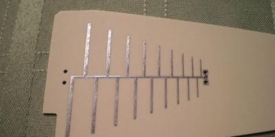
The log-periodic UHF antenna is a broadband device. Catches the entire range. The configuration resembles a wave channel, but differs in that the directors are located according to a different mathematical law, which gave the design name to the UHF antenna. Let's outline the directors with a triangle. UHF antenna Delta N111-01 is made in a similar way. Providing broadband.
A do-it-yourself UHF antenna is made from scrap materials; many metal objects can be used. The indicated designs are part of all schemes; highly specialized devices work best today. Digital multiplexes occupy only one frequency. UHF-MV television antennas are becoming unnecessary.
We wish good luck to radio amateurs; Fortune's help will be needed, given the absurdity of the articles on the topic of design. We don’t pretend to be perfect, but at least we try!
Decimeter waves with a length fall within the range of 10 cm - 1 m. This feature serves as the basis for naming devices. At frequency, electromagnetic oscillations propagate predominantly in a straight line, avoiding going around the earth's surface, and are partially reflected by the troposphere. Therefore, long-distance UHF communication is difficult; the range does not exceed 100 km. Can a decimeter antenna be assembled with your own hands? Maybe it is being actively collected by amateur engineers.
Beer cans will receive television broadcast
UHF frequencies are located in the range 300 MHz - 3 GHz. This includes many commercial, public channels.
The program “Cheap and Cheap” taught Muscovites how to catch Channel One. According to available data, it is transmitted by the HF band, the sound is adjacent to FM radio stations, the homemade design demonstrated by the presenter is used by the UHF.
You will need two beer cans with a capacity of 0.5 liters (larger volume, lower received frequencies). You can save money by buying mineral water and juice in cans. To attach the mentioned containers you will need a frame.
Channel One recommends using a wooden board 10 cm in diameter; enthusiasts have come up with a constructive solution. It is proposed to hang the jars on an ordinary wooden hanger. An indoor decimeter antenna made in a similar way can easily be placed on a window handle or a wall nail.
In addition to two beer cans you will need:
- A pair of sharp screws (screws) with a diameter of 2-3 mm, a screwdriver.
- A piece of coaxial cable from the antenna location to the TV.
- One standard jack connector.
- A roll of adhesive tape, insulating tape.
- A soldering iron, rosin, solder, and a pair of terminals for the screws indicated in step 1 will come in handy.
You should start by sealing the connector and terminals into the wire. The first will be located on the TV side, the second - on the opposite end (core, screen). Both terminals must be separated by 12 cm.
The design of the antenna avoids complications: the cans are secured with a horizontal crossbar with their necks facing each other at a distance of 75 mm from each other. Assembly begins by attaching the terminals to the necks with screws. There is no need to tighten it all the way, the wires should be pressed tightly against the cans.
The containers are secured parallel to each other with tape on a hanger. The homemade decimeter antenna is ready. Having hung the hanger in the place of best reception - first you need to find one - cover it with a curtain and clothes. According to eyewitnesses, the design works, equipped with cans of a more modest displacement. You can actively experiment by changing the distance between the containers and visually assessing the image quality.
Standard TV wire ring
The design will not require anything other than a coaxial cable with a resistance of 75 Ohms (RK 75). An even ring is bent from a piece 530 mm long and reinforced with plywood and plexiglass. High input impedance will not allow you to create a direct connection to the TV; a special matching device is used - a U-elbow.

A piece of cable 175 mm long is bent into a U shape. The ends are aligned with the edge of the wire going to the TV on both sides. The structure is fastened with tape or any other suitable material. Three screens are soldered to each other. The conductors of the U-elbow are connected to the screen of the curved ring on both sides, the central wire of the television cable - on one side.
The result is a passive UHF antenna. For outdoor use, coat the cable with a compound, resin, and enclose the product in a durable, impermeable plastic casing.
Wi-Fi, TV rings
Two aluminum circuits
“Cheburashki” firmly captured oblivion, but it turned out not completely. Many people have seen a flat aluminum plate equipped with huge rings on the sides. How to make a decimeter antenna with your own hands? You will need two flat aluminum rings with an outer diameter of 100 mm and an inner diameter of 38 mm. Each is cut through with a 5 mm wide slot.
It turns out that two circuits will avoid the use of a transformer. The frame will be a fiberglass lath, a piece of durable board. Both rings are attached with a distance between centers of 103 mm towards the slots. The upper and lower edges of the slits are connected in pairs. The screen and the core of the coaxial cable going to the TV are connected to the resulting pairs.
The antenna decorates the balcony, room, roof. The length of the coaxial cable to the TV is shorter, the reception is more reliable.
The circuit is formed by circular vibrators. With horizontal polarization of the wave, there is no phase difference between the symmetrical rings located one above the other, the cable removes the received radiation from the isthmus.
The resonant frequency of the product is 802 MHz, allowing the use of Wi-Fi networks of 900 MHz, viewing television channels 38 - 64. The UHF antenna fits perfectly with the RK-75 coaxial cable and demonstrates a gain of 15 dB.
The structure is positioned vertically, the slots should be one above the other, respectively, the polarization of the received signal is horizontal.
Two getinax circuits
Radio amateurs may find another method of manufacturing the described design attractive: the required shapes are cut out on the getinax board, textolite with one-sided foil. Between the rings, according to the described scheme, it is necessary to leave a contact bridge with an external width of 20 mm and a 5 mm slot inside. Two mirrored holes are drilled for the coaxial cable.

The method is convenient: four fastening grooves cut into the getinax by the edge of the sheet will allow you to firmly secure the product. Use:
- wall;
- frame;
- roof.
The design is easily transposed to high and low frequencies by changing the geometric dimensions of the circles. It is easier to select the optimal input impedance empirically (by trying practical dimensions).
Sealing is carried out with plexiglass plates equal in size to getinaks. The perimeter of the gap is sealed with liquid nails.
An interesting feature of the antenna type is the possibility of creating a phased array. Two identical structures are mounted vertically above each other, separated by a verified distance (the described example is 406 mm between the centers of the eights). To create a single grid, a summing device is used, formed by two branches 325 mm long, fastened in the middle. The coaxial cable is soldered to the connection point.
One circuit with transformer
Now that it is clear how to make a decimeter antenna, let’s consider the transformer mentioned above, which provides galvanic isolation of the antenna and TV circuits. The basis is the design described above. There is only one circuit, both ends are closed to the primary winding of a miniature transformer, and the coaxial cable of the TV is soldered to the secondary winding.
The core, formed by several turns of wire, plays the role of a matching device. To manufacture a hinged element, it is necessary to take a ring core with an outer diameter of less than 10 mm and a thickness of 2-3 mm. With a wire with a diameter of 0.2 - 0.25 mm, two windings are wound side by side, each with several turns.
The design is not inferior in efficiency to the dual-circuit models described above. Polarization - horizontal (the slot should be positioned vertically).

Digital television
UHF antennas for digital television are relatively simple to manufacture. You will need a wooden square with a diagonal of 200 mm, or a similar object made of plexiglass, and a large piece of ordinary RK-75 cable.
The option under consideration is part of a zigzag antenna, it perfectly serves the reception range of digital channels, regardless of the presence of direct visibility to the tower. To improve performance, you should purchase an amplifier.
The tip of the wire is stripped to 20 mm. Then a square with a diagonal of 175 mm is bent from the cable. The end is bent outward by 45 degrees, the beginning is bent, stripping an area of 20 mm, and tightly wound to the end. Reliable contact between the screens is ensured. The end of the vein hangs in the air.
At the corner opposite to the beginning, the protective layer is cut off, the screen in an area of 20 mm will be the top of the antenna. The cable square is symmetrically fixed around the perimeter of the wooden sheet. In the area where the screens meet - where the beginning and end are wound to each other - thick copper wire staples are used for fastening to improve electrical contact.
This is how you make a UHF antenna with your own hands. For outdoor use, it must be protected by a plastic case against the influence of the external environment, or securely hidden by the opening of the attic window. The signal rarely passes through metal, tiles, slate. If the roof is made of PVC, plastic, fabric, or similar materials, it is permissible to place the product in the attic.
To block the multipath effect, a reflector shaped like a piece of wood is used. It is secured with ebonite struts coaxially with the antenna.
The designs considered are designed to receive waves with linear polarization. The use of helical antennas may be necessary.
The article is devoted to an antenna suitable for various conditions for receiving a television signal: city, open space, long-distance reception. The antenna design has proven itself well in receiving an analogue television signal for three years. Excellent results were obtained when receiving digital television broadcasts.
The quality of television signal reception depends on many reasons. In urban conditions, the interaction between the main wave of the TV signal and reflected waves is low. With direct visibility between the receiving antenna and the transmitting antenna, the main wave and waves reflected from the ground, squares, streets, and roofs of buildings arrive at the receiving point. For radio waves, a large modern city is, figuratively speaking, a pile of “mirrors” and “screens,” which are bridges, factory chimneys, and high-voltage lines. High-rise buildings, like a passive repeater, re-radiate waves from the transmitting antenna. The nature of radio wave propagation is very complex, even close to the transmitter. In the radio shadow of obstacles, a weakened useful signal is received, reflected signals, noise and interference become more noticeable. In wet walls of houses, in wet trees, the signal is weakened more strongly. The maximum attenuation of the signal received by an antenna located in the radio shadow of trees occurs in the summer. Adding and subtracting the main and reflected radio waves results in the strengthening of some television signals and the weakening of others.
Loop antennas in these conditions give good results due to the attenuation of reception in the lateral and reverse directions, they are less susceptible to the influence of electrical interference and, in particular, interference from the ignition of internal combustion engines.
For long-distance television reception, the most stable image is provided by loop antennas, one of which is described in this article.
Antenna parameters
Frequency range of received signals, MHz……530 - 780
Main received television channel ....38
Range of received television channels…30 - 57
Polarization of received signals………horizontal
A “triple square” antenna is often made from a wide variety of loop antennas for the UHF range. What to do if the triple square gain is not enough, and other antenna designs are not suitable for the range of television channels of interest? At the same time, there is absolutely no place to get a sufficient number of aluminum tubes of the required diameter and specific fasteners; there is no way to assemble and install an antenna, the dimensions of which are measured in meters. Can I use an antenna amplifier that will amplify the main wave of the TV signal along with the reflected waves received by the antenna? The solution to this problem was to combine four triple squares into an antenna system - a phased array. The antenna gain is much greater than a single triple square, and the dimensions are quite acceptable. The dimensions of the design of one of the four triple squares are shown in the figure.
To make a triple square, you will need galvanized steel wire with a diameter of 3 mm. Galvanized wire is a wire that has a tin coating. Such wire is easier to coat with solder and does not rust in the open air. To make one triple square, 2 meters of wire are required. The piece of wire should not have sharp bends, dents, scratches, rust or other defects. Before making the antenna, the wire blank is thoroughly wiped using a solvent. The wire is bent according to the pattern showing the triple square construction. The wire joints at the top of the squares are soldered. Sections of the wire at the joints are coated with flux prepared from hydrochloric acid by etching with zinc. Using a soldering iron with a power of forty watts, or better yet sixty watts, areas are covered with low-melting solder, as much as the power of the soldering iron allows. Then the joints are pulled together with one or two turns of tinned copper wire with a diameter of 0.6-1 millimeter and soldered again. Finally, the joints are well soldered over the burner of a gas stove, using solder and rosin. The remaining rosin is removed from the resulting structure and washed off with a solvent. The junction must be well covered with tin, ensuring reliable contact and mechanical strength. Triple squares cannot be painted or varnished.
Before combining triple squares into a phased array, each must be tested and adjusted. Testing and adjustment is carried out indoors. A television coaxial cable with a characteristic impedance of 75 Ohms is connected to the triple square as shown in the figure. The image on the TV screen when setting up the antenna indoors can be black and white with a lot of noise. The triple square setting is performed based on the least amount of noise on the TV screen. If one triple square does not produce a color image, it doesn’t matter; when combined into a phased array, the image quality will improve significantly. Having connected the triple square to the antenna input of the TV, you need to find the point of soldering the cable to the lower vertical part of the antenna structure, moving the connection point vertically. When moving the connection, the cable center core and cable shield must be connected at the same level. In some instances of the triple square, the best image on the TV screen can be obtained by soldering the cable almost at the closing horizontal section at the very bottom of the antenna, in other instances as shown in the figure, in the third instances in the middle. Each triple square has its own optimal cable connection point. After completing the setup and checking the triple squares, it is important not to mix up the cable connection points. To obtain good quality antenna performance, you should make 6-8 triple squares, from which select four that give the best results.
The triple squares, which are phased array elements, are connected by a coaxial cable. The basis of the antenna design is a wooden frame. The length of the vertical cable sections connecting two triple squares is selected experimentally. It is impossible to accurately determine the length of cable sections in advance due to differences in the parameters of different types of cable and the unpredictable properties of manufactured triple squares.

Two triple squares are secured by wrapping a polyvinyl chloride tube on one vertical frame element, which is a wooden block. Alternately, identical sections of cable with a length of 220, 240, 260,280, 300 millimeters each are connected to the triple squares. The opposite ends of the cable sections are connected screen-to-screen and core-to-core and connected to the cable going to the antenna input of the TV. Based on the best image quality, the length of the vertical cable sections connecting the two triple squares is selected. The main contribution to the adjustment is the length of the cable sections compared to the distance between the triple squares. When setting up, you can shorten or increase the distance between the triple squares, but this will not give much effect, so the distances between the triple squares are not shown in the design figure. The image on the TV screen should be better than with a single triple square reception.

The frame is temporarily assembled from four wooden blocks fastened together with rope. Four triple squares are installed on the frame, connected by vertical cable sections. The length of two identical horizontal sections of cable connecting the vertical sections with the cable laid to the antenna input of the TV is determined experimentally. For final adjustment, two identical horizontal segments of length 130, 150, 170 or 190 millimeters are soldered alternately.
For the final production of the frame, you will need four wooden blocks 8-11 millimeters thick, 60-70 millimeters wide, 520 millimeters long, and three wooden blocks of the same thickness and width 490 millimeters long. The ends of the bars are coated with epoxy resin and dried for five days, then the entire surface of the bars is covered with epoxy resin and dried for five days. After coating with epoxy resin, the wooden blocks are painted with nitro paint at least twice. Before installing the triple squares and cable sections that combine the triple squares into a phased array, the first part of the frame is assembled from two vertical and two horizontal bars. The contacting surfaces of the bars are coated with epoxy resin, connected with screws and dried for at least three days. After the epoxy resin has dried, the two screws connecting the upper horizontal bar with the vertical bars are unscrewed. The four screws securing the central horizontal bar remain.

Triple squares connected by pieces of coaxial cable are installed on a wooden frame. The triple squares are attached to the frame with several turns of PVC tubing. A cable leading to the TV of the required length is soldered to the antenna.

For correct phasing of the antenna system, the central conductors and screens of the coaxial cable sections are connected to triple squares in accordance with the phasing diagram. The end of the cable connected to the antenna is enclosed in a PVC tube with a diameter of 10-12 millimeters and a length of about three meters to protect the antenna cable from weather influences. The PVC tube and cable are secured with a thread to a horizontal bar. The soldering of the screen and the central core of the cable sections is insulated from each other using electrical tape. Two vertical bars are installed on top of the installed triple squares and cables, and one horizontal bar is placed on top of them in the center. The frame parts are connected with screws with a diameter of 6 millimeters. When installing screws, use the holes left after unscrewing the screws connecting the top horizontal bar to the vertical bars. Sections of coaxial cable and parts of triple squares are enclosed inside a wooden structure, which reliably protects the soldering points from weather influences.
The gaps between the bars at the sides and ends are sealed using construction sealant “liquid nails”.

The antenna is installed on the mast using clamps corresponding to the diameter of the pipe. Screws pass through holes in the horizontal bars. The antenna is fixed at two points. By loosening the clamp screws, you can accurately align the antenna with the transmitter.

Galvanized wire, a pipe clamp, epoxy resin, and paint can be purchased at a building materials store. A coaxial television cable with a characteristic impedance of 75 Ohms should be selected with a central copper core and a double shield consisting of foil and braided copper cores. The best results can be obtained by using the largest diameter cable with the largest possible number of cores in the screen braid.
The distances between the elements of the phased array, the dimensions of the triple square and the length of the cable sections were selected through numerous experiments in order to ensure the reception of the largest possible number of television channels and at the same time the minimum possible dimensions, reducing the weight of the antenna and facilitating installation. Reception to the antenna is possible through obstacles from nearby trees. The antenna has a low windage. Thanks to the arrangement of the cables inside a sealed wooden frame, a long service life and protection from weather factors are ensured. The quality of the received image does not depend on the time of year or time of day.
We will send the material to you by e-mail
In the modern world, there is a significant range of high-tech and functional antennas for installation at home. But there are times when the TV has stopped showing in a country house. Some craftsmen find a way out of this situation and make something that helps correct the situation. Moreover, they give recommendations to others: how to make an antenna with your own hands for a TV. Let's look at simple methods that may be useful to you.
Homemade devices are especially good when they are needed for temporary use
The simplest and most unusual option to construct an antenna is from beer cans. And according to experts, as many as seven channels will be shown. To build such a structure, prepare:
When deciding how to make your own antenna for a TV, keep in mind that the gap between the end parts of the cans should be about 75 mm. And the best location of the structure is near the windows.
The stick that will be used for the antenna should be made of wood. You cannot take aluminum or titanium options. Cable parts can be soldered. Instead of tape, you can use electrical tape or even a band-aid. Containers for creating the device must be thoroughly washed and dried. To improve image quality, you can “play” with the distance between the banks.
Table 1. Antenna made from beer cans
| Image | Stages |
|---|---|
 | Prepare the cable. To do this, make a cut on one edge and remove the insulation layer. Then the middle layer is cut off. A plug for the TV antenna is mounted at the other end. |
 | Stock up on cans. Their capacity should be 1 liter! |
 | Make contacts. One end of the twisted cable is mounted to the can, and the other with a copper core to the other. Fastening is carried out using a screwdriver and a soldering iron. |
 | Assemble the antenna. A trempel is used as a supporting device. |
 | Set up your device. |
Related article:
In the article we will look at the application features, types of devices, secrets of selection and installation.
Is it possible to make a homemade antenna for digital television from wire?
A good way is to use copper wire to create an antenna. For such a mechanism you will need an amplifier, wire, sheet of metal, drill, bolts, metal pipe, cable and hammer.
To make such a homemade home antenna for a TV, we perform the following operations:
- At the first stage we make a catcher. To make it, the wire must be bent so that all sides have a length of 45 cm;
- Next, we fix the wire on the plate. In this case, a connection is made to the plate;
- cable is connected;
- A mast is made from a metal pipe. Its foundation needs to be buried.

Helpful information! All details should be painted over. This will protect the product from corrosion and aggressive operating conditions.
DIY antenna option for digital TV HDTV
There are various methods for making a TV antenna with your own hands. The first two methods we considered operate at a frequency of 270 MHz. And the next option has great possibilities. In this case, the picture will be of higher quality, since the signal can reach 490 MHz. You will definitely need a special transformer, which is unlikely to be found among the materials at hand. Such a device should be purchased in advance. There are also methods for making a transformer yourself, but they are quite complicated. The materials you should prepare are cardboard, tape, foil, stapler, marker, tape measure and glue.
- First, you should print a special diagram for installing such a device. According to the diagram, all structural elements are cut out, as well as all the necessary foil parts. Then you need to make a butterfly out of cardboard and paint over individual parts with a marker.
- The next step is to build a reflector, the size of which is 35-32.5 cm. One of the sides is glued with foil.
- Rectangles of the same size are cut out in the middle. They are needed to construct a catcher for the structure. The length of the plate should be about 35 mm. This product is designed to maintain the distance between additional elements and the reflector.
- The individual parts are glued to the rectangular element. Then the recesses for the cable are drilled.
The correct instructions will tell you how to make an antenna for a TV with your own hands. A transformer must be connected, and the cable must be installed in the plug. This method is only suitable for indoor use, as the paper will quickly become unusable outdoors.
The table details all stages of installing such equipment.
Table 2. DIY antenna for digital TV HDTV
| Image | Stages of work |
|---|---|
 | Prepare the necessary material. |
 | Print the template and cut it out. |
 | Cut out a reflector from cardboard and then cover it with foil. |
 | Cut out rectangles in the middle. |
 | You also need to cut out all the necessary parts from cardboard. This applies the template. |
 | It's better if you make all the details in color. |
 | Foil is also cut using stencils. |
 | To create a bend, a small undercut is made on the dotted line. |
 | Foil is glued to individual antenna elements. |
 | The antenna is being assembled. At the same time, measure 35 mm from the reflector and glue the butterfly. |
 | A hole is made in the middle of this element for the passage of the cable. |
 | A suitable transformer is installed and the antenna is ready. |
Related article:
This article talks about what parameters a high-quality TV stand has, and photos and descriptions will help you choose the best option for your interior.
Nuances of the apartment option
When making some types of structures, you can make an antenna amplifier with your own hands. Try to make a high-quality amplifier from scrap materials that can be used for both outdoor and indoor use.
To carry out the work you will need the following materials:
- copper wire, the length of which is 4 m and the diameter is about 4 mm;
- board of any thickness with a width of 70 mm and a length of 550 mm;
- screws and screwdriver;
- plug and soldering iron;
- pencil and ruler.

Follow the drawing. Start by drilling holes in the surface. The parameters from the diagram are transferred to the board, and drilling is performed in certain places. The copper wire is measured and cut into 8 equal sections. In the middle of each segment you need to remove the insulation.
It is not difficult to buy an antenna for a television receiver. An extensive range is offered both in terms of design diversity and signal reception parameters. But in some cases it doesn’t hurt to know how to make the device yourself.
For example, you want to watch TV at your dacha, but there is no corresponding store nearby. Or the existing device receives few channels and the image quality is poor. Self-assembly of the antenna is also useful for educational purposes, when the principle of its operation becomes clear.
A simple option: an antenna made from cans
The simplest antenna that you can make yourself is a design made from tin drinks cans. Such material is available, and production takes no more than 20 minutes if you have the skill. In addition, it gives good results in signal reception, working better than some stationary antennas.
In order to make an antenna from cans, you need to prepare the following components and tools:
- a cable having a length from the TV to the window and slightly longer;
- two tin cans;
- two self-tapping screws;
- plug for inserting the cable into the TV socket;
- insulating tape;
- screwdriver;
- wooden, plastic pin or stick - the basis for attaching cans and cables.
Manufacturing is carried out as follows:
- It is required to fasten the stick and cans at a distance of 7 cm from each other, using insulating tape and a small stick. The cable must be stripped from one end so that when the wires (central and side) are separated there is a distance of 7 cm. Then it can be attached to the rings of the cans, if any.
- If the cans do not have rings, screw in screws. At one end we attach the stripped cable wires to the screws. There is a third way - you can solder them. We attach the cord itself, as well as the edges of the cans separated by 7 cm from each other, to the same stick with insulating tape or tape for stability. The free end of the cable must be equipped with a plug.
- The antenna can work in the room. If you need to take it outside the window, we protect it from atmospheric conditions: cover the tin cans with plastic bottles (2-liter containers), cutting off the bottom and neck of them. In the center of the plastic structure we make a hole through which we thread the cable. After connecting, you will need to treat the holes with boiling water to make them sealed.
- The antenna operating in the UHF range is almost ready. You just need to connect it and configure it (turn on auto channel search).

Wire antenna
For the simplest wire antenna, copper or brass wire is used, which does not oxidize too quickly. It is stripped of insulation from both ends. One end will be intended for the TV socket, and the second is attached to the pipe, battery.
You can really pick up a signal with such an antenna, because the pipes go to the roof and amplify the signal. But the number of channels will be no more than 5.
Another case is to stretch the wire to the balcony, for which it must be of sufficient length. Here it can be secured on a clothesline. The image will have better quality than in the previous case, and the number of channels may increase. These are options for manufacturing the most economical antennas.

We use tubes
Antenna parts can consist of a variety of metal profiles, for example, tubes. It is better to use thin-walled materials for the correct flow of high-frequency currents. It also reduces the weight of the structure.
You can make a simple antenna yourself from two identical tubes. It will be able to receive a signal in rural areas at a distance of 30 km from the repeater. The tubes are connected by a cable, the free end of which is connected to the TV.
First you need to find out the broadcast frequency of the TV tower located closest to your home. Based on this, the length of the tubes is selected. The television wave range is 50 – 230 MHz. The entire strip is divided into 12 channels, for each of which the vibrator tube must have its own length.
So for 50 MHz it is 276 cm, and for 223 MHz it is 66 cm. The length of the loop connecting the cable tubes is also proportionally calculated: the lower the frequency, the greater its length.
The following materials and tools are required:
- Two identical pipes with a diameter from 8 to 24 mm: brass, steel - any metal.
- A cable with a resistance of 75 Ohms of the required length (from the TV to the antenna + 2 meters).
- Textolite or getinaks with a thickness of more than 4 mm. Clamps for attaching pipes.
- The rod is the basis for placing the structure.
- Soldering iron, flux, solder, epoxy resin or electrical tape.
Assembly steps
- You need to cut a pipe with a length selected according to the frequency of the television center, and then divide it in half and flatten each part on one side for attachment to the PCB. The distance between the tubes is approximately 7 cm - optimal for good reception. The structure is then securely attached to the holder with clamps.
- The vibrator is installed on the mast and both pipes are connected with a matching device - a cable loop with a resistance parameter of 75 Ohms. The cores are soldered to the tubes, and the braid is connected with a conductor. To do this, you can take a piece of cable and peel off the insulation.
- The central wires from the matching loop and the cable to the TV are also connected, and then their braids using copper wire.
- The TV loop and cable are attached to a rod, which is positioned at the desired height where the adjustment is made. Having caught a good signal, the antenna is fixed. To find out the approximate direction, you can look at the antennas of neighboring houses.
The design of curved tubes is even more effective. But manufacturing such parts is fraught with difficulties.

Improved options
Sometimes an antenna in a country house receives no more than 2 channels. In a short time you can improve the quality of its work. The reason for poor reception is the significant distance of television signal stations. You can use an existing device as a basis.
And also make something new from existing household items:
- You need to take a wire with a diameter of one and a half millimeters, up to 2 meters long, if the antenna is up to 6 meters.
- 1.5 meters of wire twisted in a ring with a diameter of up to 45 cm.
- The second one is also made from wire ring up to 18 cm in diameter.
- The rings are secured by securely fixing them to a piece of plywood, wood or plastic. The antenna is then installed on the roof.
- When setting the location of the rings should be directed towards the signal. To find it, you need to rotate the antenna using an assistant checking the image quality. After setting up the reception, you can use the television system and watch programs.
You can try making a satellite dish from a bucket lid attached to a stick (mast). To do this, you also need a head from an old broken satellite dish, which is attached with wire to a stick.
The cover serves as a reflector, which is attached to the same pin to the wire from the head from below. The head is located towards the reflector, and the second cable extending from it goes to the signal receiver - the TV.
Rules for installing homemade devices
Before you make an antenna yourself, you need to decide on its type. A parabolic design is suitable for satellite reception; making it yourself is not so easy.
Therefore, there are different types of antennas:
- zigzag;
- frame;
- from wave channels;
- vibrators;
- traveling wave catchers;
- as a combination of structures.
The signal receiving circuit or other structure is connected to the television receiver with a cable with a plug at its end. The winding needs to be bent, after which a wire will appear. Both are attached to the plug using screws, if it is equipped with such fasteners.
Or simply insert the central wire into the plug hole, and the winding is also placed inside. The second end of the cable, stripped and twisted into a ring, should be attached to the circuit. For reliability, you need to wrap the attachment point with insulating tape.
When using external structures located on the roof of a house or balcony, it is necessary to adjust the received signal. To do this, the antenna is rotated in different directions until the image is of the best quality. You can look at the neighboring houses for approximate direction.

Signal amplifier
To improve a weak signal, an amplifier is used, which can be purchased. The use of this device is appropriate if the antenna does not quite match the type or the television center is located far away. Then there is quite a lot of noise on the screen, and the image is almost the same.
An amplifier is used only when it is impossible to improve the antenna itself in terms of efficiency. The choice of this part depends on the required parameters, taking into account the distance to the broadcast center.
Antenna amplifier boards are characterized by a gain that allows receiving transmissions at a distance of up to 150 km. When purchasing, you need to indicate the type of antenna, for example, mesh or circuit. The device is installed on the antenna using nuts.
It is often necessary to provide the board with a sealed shell that protects it from natural factors: foil or polyethylene. It is best to place an antenna with an isolated amplifier on the roof of the cottage, facing the nearest television tower.
- Before you decide to build an antenna on your own, you need to clarify the operating principle of the specific television receiver for which it is intended. Today, analogue TVs are being replaced by digital ones. An outdoor antenna for a digital receiver does not need to provide a wide band, since only resonance is required at the required parameters.
- Modern broadcasting is mastering UHF frequencies (300-900 MHz) with horizontal polarization. To implement such tasks, a paraboloid antenna with a tuned feed would be suitable. But then you will need direct access to the telecentre tower or tuning to a weather-dependent reflected signal. Therefore, the paraboloid is not always suitable for picking up terrestrial broadcasts, but is appropriate for receiving a satellite signal in the presence of line of sight.

The era of digital signals has arrived. All broadcast television companies began to work in a new format. Analog TVs are reaching their end. They are still in working order and are found in almost every family.
In order for older models to successfully complete their service life, and for people to be able to use them when watching digital broadcasting, it is enough to connect the DVB-T set-top box to the TV receiver and pick up the TV wave signals with a special antenna.
Any home craftsman can not buy an antenna in a store, but make it with his own hands from available materials for watching digital TV programs at home or in the country. The two most accessible designs are described in this article.
A little theory
Operating principle of an antenna for digital packet television
Any television signal propagates in space from the emitters of the transmitting television tower to the TV antenna by an electromagnetic wave of a sinusoidal shape with a high frequency, measured in megahertz.

When an electromagnetic wave passes through the surface of the receiving beams of the antenna, a voltage V is induced in it. Each half-wave of a sinusoid forms a potential difference with its own sign.
Under the influence of an induced voltage applied to a closed receiving circuit of the input signal with resistance R, an electric current flows in the latter. It is amplified and processed by the digital TV circuit and output to the screen and speakers as image and sound.

For analog models of TV receivers, an intermediate link works between the antenna and the TV - a DVB-T set-top box, which decodes digital information of an electromagnetic wave into a normal form.
Vertical and horizontal polarization of digital TV signal
In television broadcasting, state standards require electromagnetic waves to be emitted in only two planes:
- horizontal.

In this way, transmitters send emitting signals.
And users simply need to rotate the receiving antenna in the desired plane to maximize the power potential.
Requirements for a digital packet television antenna
TV transmitters propagate their signal waves over short distances, limited by the line of sight from the top point of the TV tower emitter. Their range rarely exceeds 60 km.
For such distances, it is enough to provide a small power of the emitted TV signal. But, the strength of the electromagnetic wave at the end of the coverage area should form a normal voltage level at the receiving end.
A small potential difference, measured in fractions of a volt, is induced at the antenna. It creates currents with small amplitudes. This imposes high technical requirements on the installation and quality of manufacturing of all parts of digital reception devices.
The antenna design should be:
- manufactured carefully, with a good degree of accuracy, eliminating loss of electrical signal power;
- directed strictly along the axis of the electromagnetic wave coming from the transmitting center;
- oriented according to the type of polarization;
- protected from extraneous interference signals of the same frequency coming from any sources: generators, radio transmitters, electric motors and other similar devices.
How to find out the initial data for calculating an antenna
The main parameter influencing the quality of the received digital signal, as can be seen from the explanatory first figure, is the length of the electromagnetic wave of radiation. Under it, symmetrical arms of vibrators of various shapes are created, and the overall dimensions of the antenna are determined.
The wavelength λ in centimeters can be easily calculated using a simplified formula: λ=300/F. It is enough just to find the frequency of the received signal F in megahertz.
To do this, we will use a Google search and ask it for a list of regional TV communication points for our area.
As an example, a fragment of a data table for the Vitebsk region is shown with the transmitting center in Ushachi highlighted in red.

Its wave frequency is 626 megahertz, and its polarization type is horizontal. This data is quite sufficient.
We carry out the calculation: 300/626=0.48 m. This is the length of the electromagnetic wave for the antenna being created.
We divide it in half and get 24 cm - the desired half-wave length.
The tension reaches its maximum value in the middle of this section - 12 cm. It is also called amplitude. The whip antenna is made to this size. It is usually expressed by the formula λ/4, where λ is the electromagnetic wavelength.
The simplest TV antenna for digital television
It will require a piece of coaxial cable with a characteristic impedance of 75 Ohms and a plug for connecting the antenna. I managed to find a ready-made two-meter piece in the old stock.

I cut off the outer shell from the free end with a regular knife. I take the length with a small margin: when setting up it is always easier to bite off a small piece.

Then I remove the shielding layer from this section of the cable.


The work is done. All that remains is to insert the plug socket into the connector on the TV signal set-top box and direct the bare wire of the inner core across the incoming electromagnetic wave, taking into account horizontal polarization.

The antenna should be placed directly on the window sill or secured to the glass, for example, with a piece of tape, or tied to the blind mount. Reflected signals and interference can be shielded with a strip of foil located a short distance from the central core.
Such a design can be done in literally ten minutes and does not require any special material costs. It's worth trying. But, it is capable of working in an area of reliable signal reception. My building is screened by a mountain and a multi-story building. The transmitting television tower is located at a distance of 25 km. Under these conditions, the digital electromagnetic wave is reflected many times and is poorly received. I had to look for another technical solution.
And for you on the topic of this design, I suggest you watch the video by the owner of Edokoff “How to make an antenna for digital TV”
Kharchenko antenna at 626 MHz
To receive analogue television signals of various wave frequencies, the design of a zigzag broadband antenna, which does not require complex manufacturing, worked well for me before.
I immediately remembered one of their effective varieties - the Kharchenko antenna. I decided to use its design for digital reception. I made the vibrators from a flat copper bar, but it’s quite possible to get by with round wire. This will make it easier to bend and straighten the ends.

How to determine the dimensions of a specific antenna
Online calculator
Let's use the all-knowing Google search. We write on the command line: “Calculation of the Kharchenko antenna” and press Enter.

We choose any site you like and perform online calculations. I went into the first one that opened. This is what he calculated for me.

I presented all his data with a picture indicating the size of the Kharchenko antenna.

Manufacturing of antenna design parts
I took the information provided as a basis, but did not accurately maintain all the dimensions. I know from previous practice that the antenna works well in the broadband wavelength range. Therefore, the dimensions of the parts were simply slightly increased. The half-wave of each harmonic of the sine wave of the electromagnetic TV signal will fit into the arm of each vibrator and will be received by it.
Based on the selected data, I made blanks for the antenna.

Vibrator design features
The connection of the ends of the figure eight busbar is created in the center at the bending stage. I soldered them with a soldering iron.

I created it according to the “Moment” principle, made it with my own hands from old transformers, and has been working for two decades. I even soldered 2.5 square copper wire with it in thirty-degree frost. Works with transistors and microcircuits without burning them out.
In the near future I plan to describe its design in a separate article on the website for those who also want to make it themselves. Follow publications, subscribe to notifications.
Connecting the antenna cable to the vibrator
I simply soldered the copper core and braid to the metal of the figure eight from different sides in its center.

The cable was tied to a copper bar, bent into a loop in the shape of a semi-square vibrator. This method matches the resistance of the cable and antenna.
Screening grid design
In fact, the Kharchenko antenna often works normally without signal shielding, but I decided to show its manufacture. For the base I took a wooden block. I did not paint or varnish: the structure will be used indoors.
In the back side of the block I drilled holes for attaching the screen wires and inserted them, and then wedged them.

The result was a screen for the Kharchenko antenna. In principle, it can be made of a different design: cut from a piece of frontal armor of a tank or cut from food foil - it will work approximately the same.

On the back side of the bar I secured the vibrator structure with a cable.

The antenna is ready. All that remains is to install it on a window to work in vertical polarization.

When a television receiver is located at a great distance from the transmitting generator, the power of its signal gradually weakens. It can be increased by special electronic devices - amplifiers.
You just need to clearly see the difference between the signals received by the antenna, which can be:
- simply weakened;
- contain high-frequency interference that distorts the shape of the digital sinusoid into the shape of some kind of “doodleball”.
In both cases, the amplifier will fulfill its role and increase the power. Moreover, the TV will clearly perceive and display a weakened signal, but with an amplified signal, playback problems will arise.
The waves are designed to eliminate such interference:
- high-pressure filters;
- screens.
They must be measured with an oscilloscope, and the methods of using various designs must be analyzed individually in each specific case. The antenna is not to blame here.
A homemade television antenna is configured to receive over-the-air signals no worse than purchased ones. However, it is distinguished by great quality and efficiency.
Any craftsman can make such a device from scrap materials and install it in a suitable place.

Briefly about modern antennas
Modern receivers operate in the UHF range and are characterized by a high level of signal propagation and the use of low-power sensors.

However, digital television broadcasting is becoming the most popular, which has a number of advantages:
- Resistance to interference or other cable distortions;
- High image clarity and sharpness;
- Ability to select the most interesting channels.
- The simplicity of the design allows you to make such equipment at home and using available materials.

Types of antennas
There are a large number of antenna device options, each of which has its own advantages and disadvantages. Before you start making the receiver, you need to decide on the type of model: all-wave, speech therapy or zigzag.

You can make an all-wave antenna in an hour and from cheap materials. It is frequency independent and perfectly receives the signal within the city, but in settlements remote from powerful receivers it will be useless.
The speech therapy antenna is universal, but not rich in a large number of received channels.

The simple design and average characteristics ensure stable reception.

A Z-shaped antenna will require a large amount of time and materials, which pays off in a wide receiving range.

Required level of training
Despite the simplicity of most antennas, sufficient experience and knowledge of higher mathematics and electrodynamics are still required. This knowledge will help you better understand diagrams and drawings and understand all the terms used.

However, even unprepared but motivated craftsmen have a chance to assemble a high-quality digital antenna.

First of all, you need to familiarize yourself with the photo of the antenna device and the basic terms found in the instructions:
- “KU” – designation of the device’s power strength, indicating the ratio of the received signal to its main “lobe”;
- “KND” is the coefficient of proportion of the area of the antenna’s body circle to the level of inclination of the angle of all lobes of the device;
- “KZD” – correlation of the signal received on the main sheet and the total power of the device.

The following points should also be considered:
- The power of a band antenna depends on the level of the useful signal.
- These characteristics are not always interrelated, which requires special attention when setting up equipment.
- Each element of the device is securely welded or soldered to its neighbor.
- Street units are thoroughly fixed with all kinds of fastenings.
- In places of zero potential, it is mandatory to use solid bent metal.
- Coaxial cable or other corrosion-resistant coaxial cable is most often used as the central core.
- It is recommended to connect the elements with a 40 V soldering machine, while using low-melting solders and flux paste.
- For an outdoor antenna, it is necessary to set up high-quality protection of connections from precipitation, temperature changes and other negative natural influences.

All-wave antenna circuit
To make an all-wave digital antenna you will need 2 triangular metal plates or square fiberglass with a reflective coating, as well as 2 wooden slats with a cross section of 2-3 cm and wire.

- Prepare all the necessary materials and tools, including a soldering or welding machine, wire, ruler, meter, pliers, safety glasses, rope, scissors.
- Place the plates at an angle of 90 degrees so that the width of the device is equal to the height.
- Fix with a soldering iron.
- Attach the cable to the point of zero potential, but do not solder it, but tie it.

Beer can antenna
Beer or soda cans have good reception of digital television signals, which makes them an excellent material for a homemade antenna.
Note!


This material is used to increase the diameter of the arms on a linear vibrator, which enhances the signal quality and makes it possible to connect directly to the cable.
Optimization of an old antenna
To receive a higher-quality digital signal, you can upgrade your analog television antenna and make a T2 receiver out of it. The main requirement will be strict adherence to all dimensions of the equipment: the outer side of the square is 14 cm, the inner side is 13 cm, a gap of 2 cm and a wire 115 cm long. Next, all elements are cleaned, soldered and connected to the television cable.

Having understood the principle of operation of the antenna, you can experiment with its design, tuning into new channels and improving the quality of already received ones.

You can use any materials at hand, for example, to make an antenna for a modem, a box of laser discs will be useful.

DIY antenna photo


Note!


Note!