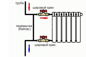
Parallel- with this method, the elements included in the chain are combined by two nodes and are not connected to each other. With this connection of the elements, even if one of the lamps burns out and breaks the circuit, the others will not go out, since the current will have “bypass” paths.
Sequential- all elements of the chain are located one after another and do not have nodes. An example of a series connection is the well-known Christmas tree garland: a large number of light bulbs connected by one wire. If one burns out, the circuit will break and all will go out.

There are three main types of electrical wiring. Let us consider them in detail, since the entire scheme depends on the selected type.
1. Star type sometimes called boxless, or European, type of wiring. Briefly, this type can be displayed as follows: one socket - one cable line to the panel. This means that each outlet and lighting point has a separate cable line that goes directly into the apartment panel and ideally has a circuit breaker. What are the advantages and disadvantages of this type of wiring? The advantage is, first of all, safety and the ability to control every electrical point. In addition, there is no need to install distribution boxes. This is exactly the type of wiring that is done when installing a “smart home” system. The downside of the “star” is at least three times the wiring consumption and, accordingly, the labor costs for its installation. In addition, the apartment panel becomes the size of an average closet. It can consist of 70–100 groups of machines, especially if the facility also has information networks. It is difficult to install such a shield yourself, and it is more expensive than a regular one.
2. Type "loop" resembles a “star”, but differs from it in its economy. You can depict it like this: socket - socket - socket - housing panel or junction box. Several electrical points are connected in series to one cable, from which a common supply conductor goes either to the apartment panel or to the junction box.
3. Type of wiring in junction boxes- the most common option. This is exactly how wiring was done in Soviet times. An economical method that does not require special costs. There is no shield at all in the apartment; it is located on the landing. An apartment branch departs from such a common supply “riser”. On it in the panel there is a meter and a circuit breaker (sometimes - 1, sometimes - 2–3, rarely more). The power cable enters the apartment, then, using distribution boxes, into the premises, approaching each point. We can say that from the junction box the wiring goes to the points in a “star”.
Pure wiring types are rarely used. Based on the available resources and at will, a mixed type is usually selected. An example of wiring in a separate apartment.
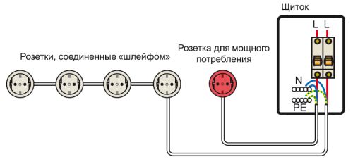
Two types of wiring: socket - shield ("star") and shield - socket - socket - socket ("loop")
The power cable goes into the apartment panel, where there are several groups of circuit breakers and protection devices. In the panel, the common cable is routed into several zones, for example, in living rooms and separately in the bathroom and kitchen, divided into sockets and lighting. The power cable of a separate zone enters the room and is distributed point by point in the box. Options are possible here: the cable will go to the sockets in a “loop” or a separate wire will be allocated to each point.

Serial "loop" and parallel in distribution boxes

Professional electricians draw up such diagrams taking into account all factors. These are the wishes of the owner of the property, that is, what exactly you want to see in the apartment or house. For example, the owner says that the living room should have two groups of sockets, three in each. Plus two pass-through switches and three telephone sockets. The electrician, having taken note of this data, draws up a diagram according to the rules of electrical installation work, which takes into account safety parameters, the order of work, the type of wiring, the dimensions of the grooves, etc. Such a drawing is a document and is certified by a special organization.

An example of a schematic diagram of the electrical supply of an apartment drawn up by a professional electrician
Modern companies providing electrical installation services use computer programs. They were created specifically for engineering and technical workers (E&T) and are unlikely to be useful to a home handyman.
To install the wiring yourself, you can draw the diagram yourself. This is done quite simply. To begin with, an apartment plan is drawn taking into account all sizes. If you do not have the necessary documentation, you can take it from the developer, although it must also be kept by the owner of the property.
Then, using special symbols, all the desired points are set: lamps, sockets, circuit breakers, etc. You must not be lazy and put in generally accepted symbols so that other people can understand this diagram. There are frequent cases when, some time later, the author of the diagram cannot understand the mysterious hieroglyphs that he himself invented. After this, lines are drawn that indicate the wiring. Be sure to indicate on the plan how far the cable is from the ceiling or floor, especially if the wiring is hidden.

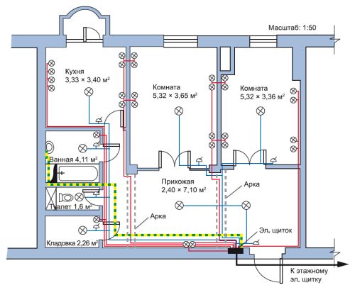
The following is an example of an apartment's electrical circuit. Lighting wires, power cables and grounding wires are shown in different colors. Conventional icons depict lamps, sockets, switches and distribution boxes. This diagram is very visual, and you can use it to perform all the necessary calculations. This is necessary in order to know exactly where the wires go in the future. Otherwise, while hanging a picture or shelf, you can hit the cable with a drill.
There are standard rules for installation. They are:
1. The wire is laid only along vertical and horizontal lines at right angles. If you want to cheat and save the cable by running it diagonally, it is better not to do so. In the future, it is very difficult to find this crooked path, and hitting it with a nail is as easy as shelling pears.
2. The distance from the wire to the ceiling or floor should be 15 cm. From corners, door jambs and window frames - at least 10 cm. When piping through heating pipes, a gap between them and the wiring should be at least 3 cm.

3. It is necessary to avoid crossing wires when laying. If this is difficult to achieve, then the distance between the cables should be at least 3 mm.
4. To simplify calculations, all sockets and switches must be at the same height. Typically, switches are installed to the left of the door at a height sufficient to touch them with a lowered palm, that is, 80–90 cm. Sockets are mounted at a height of 25–30 cm. However, in the kitchen and in the case of connecting high-hanging electrical appliances, this distance can be and others. It is best if the wire to the switches goes down from above, and to the sockets from below - this is what most electricians do.
5. The length of the conductor coming out of the electrical point should be 15–20 cm. This is done for the convenience of installing points with a hidden type of wiring. If it is an open type, then the length of the conductor may be less: 10–15 cm.
The ends of the wires that enter electrical points must be insulated with electrical tape. Armed with the drawing, you can begin installing the electrical wiring.
When changing the electrical system in an apartment, you need to know exactly where and what electrical points will be installed, so you need to start this process by developing a wiring diagram, and it cannot be otherwise. It is impossible to start installation without a diagram, one is impossible without the other, any professional electrician knows this.
When developing an electrical wiring diagram, many issues arise, such as the choice of conductor cross-section, installation location of sockets and switches, the planned load depending on the power of electrical appliances, as well as the protection of the circuit itself, electrical appliances and people from emergency operating conditions. Therefore, when repairing electrical wiring or completely replacing it, maximum attention should be paid to these issues.
If for some reason the existing wiring diagram of the apartment does not suit the owner, for example, because the current loads do not correspond to the cross-section of the conductors, the location of sockets and switches, or for some other reason, you should think about repairing the wiring and seek help from specialist electricians . Unless, of course, you yourself are an expert in this field.
Many apartments still use a circuit with aluminum wiring; at the time when it was designed and these buildings were built, there were no such large electrical loads, and the requirements for the wiring diagram of apartments were different.
The absence of a grounding conductor, the use of aluminum wires when installing wiring, the lack of high-quality protection (RCD, modern automatic machines) are the main, but far from the only disadvantages of outdated circuits. Operation of such electrical wiring can be dangerous to human life.
So, as many people install in their apartments instead of bathtubs, Jacuzzis to which a voltage of 220 V is supplied, the electrical wiring diagram of the apartment must be three-wire, have three wires phase, zero, ground, and also the line must be protected by an RCD, the same requirement applies to for other electrical appliances such as a washing machine, electric oven, dishwasher, etc. Sometimes fires occur due to a short circuit in old electrical wiring.
If all this is not indifferent to you, you should determine how old your electrical wiring is, what work needs to be done to correct the current situation, repair the electrical wiring or only partially replace it, what materials should you purchase? But it’s better to entrust all this to our professionals! What will be the wiring diagram for the apartment? It all depends on how many rooms there are in the apartment, on the power consumption, on the number of electrical appliances.
Typical wiring diagrams in an apartment.
When developing a circuit, the electrician must take into account such nuances as the location of sockets and switches in the rooms so that they are not subsequently covered by furniture. If you contact us, we will take into account all the points, grounding of electrical appliances, power and selection of conductor cross-section, installation of modern protection (RCD, circuit breakers).
So, if the apartment has a standard layout, you can use a ready-made scheme developed for standard apartments by making minor adjustments. It is shown in the figure below.
Figure 1 - schematic diagram of the apartment's electrical wiring.

Figure 2 - single-line diagram of the apartment's electrical wiring.
A mandatory requirement is the installation of a potential equalization system. To do this, it is necessary to connect the grounding bus in the electrical panel with a separate wire to the pipes of cold, hot water and sewerage, as well as to the bathroom, as shown in the diagram Figure 2. The rules for implementing the potential equalization system are defined by the IEC 364-4-41 standard and paragraphs. 1.7.82, 1.7.83, 7.1.87, 7.1.88 PUE 7th edition.
This diagram shows the connection of the apartment wiring to the three-phase power supply of the house riser. From the floor board, a VVG 5*16 cable enters the apartment board, that is, the entrance to the apartment. The input is a five-core cable from which the entire apartment is powered. N is working zero. L1, L2, L3 are phase numbers. PE is protective earth.
The distribution board in the apartment is arranged as follows: the input cable is connected to the input circuit breaker, from the input circuit breaker there are jumpers by cable or bus to the group circuit breakers, lighting network, socket network and other electrical appliances.
We are drawing up a wiring diagram for the apartment.
First, you need to find out what electrical appliances will be used in the apartment and where they will be installed. Let's start with the kitchen, since the most powerful appliances are traditionally concentrated in this place. One of them is an electric stove, onto which a separate cable is laid from the VVG 3x6 electrical panel and a separate automatic machine is installed. A separate cable is also laid directly from the switchboard to other powerful electrical equipment, such as a washing machine, dishwasher, water heater, heated floors, and air conditioning.
For the remaining sockets in the apartment, you can run a common cable to the distribution box, and from there you can wire the cable to each socket or block of sockets. We will do the same with the lighting, we will throw a common wire on the box, and from the box we will make wiring to the lamps and switches.
Thus, we get a circuit in which the power supply for the entire apartment load is divided into group lines. Such as lighting group, household socket group, power socket group.

Figure 3. Simplified block diagram of the apartment's electrical wiring.
Having drawn up a schematic diagram and knowing the area, the location of the cable, the location of the sockets and switches, you can begin to calculate the amount of materials that will be required for installation. The apartment's electrical wiring diagram will help us calculate the cable footage, the number of sockets and switches, purchase the required number and type of machines, and select an electrical panel.
Here are a couple more diagrams that will be more understandable for non-professional electricians or people with a superficial understanding of electricity. The diagram clearly shows cables, circuit breakers, as well as electricity consumers.

Figure 4. Schematic diagram of the electrical wiring of a one-room apartment.

Figure 5. Block diagram of the apartment's electrical wiring.
- Plastic shield housing
2. Clamping elements of zero working conductors
3. Clamping element of neutral protective conductors, as well as potential equalization conductor
4. Clamping element of the input terminals of protective devices of group circuits
5. Residual current switch (RCD)
6. Slot machines
7. Group lines
How to determine the layout of an existing electrical wiring.
Determining how the wiring is done in an apartment is not difficult if you know some of the rules by which it is laid. Installation diagrams may vary depending on the type of house and the year it was built, but it is still possible to determine the wiring diagram for the apartment.
In brick houses Wiring can be done in two ways. The first method is an overhead distribution no lower than 15 cm from the ceiling level. At the same level, distribution boxes are placed, from which descents to sockets and switches are made. All wires are laid strictly vertically and horizontally in the groove. Cables for lighting are laid in ceilings in which there are voids (channels).
The second method is bottom wiring, when the cables are laid in pipes along the floor and filled with screed; from the floor, the cables rise vertically to the distribution boxes and wiring is already done from them. Lighting is also provided in the ceiling ducts.
In panel houses, Khrushchev buildings Electrical wiring is carried out in the channels of the slabs. Channels for wiring, places for installing sockets, switches, are made at the factory during the manufacture of slabs. All channels converge into distribution boxes, from which channels go to the electrical panel. In panel houses, channels are often made not vertically and horizontally, but along the shortest path, that is, along an oblique line.
In some Khrushchev buildings, the wiring for powering the outlets is routed under your floor, and the wiring for lighting is under the floor of your neighbors above.
To conclude the topic, there are some useful tips. If you are doing electrical wiring repairs.
The installation height of sockets and switches from the floor level can be any, the main thing here is that it is convenient for you to use them. In general, there is a rule according to which sockets should be at a height of 30 centimeters from the floor, and switches - 90 centimeters. In general cases, this placement is usually the most convenient. But it would obviously be more appropriate to place sockets in the kitchen above the desktop surface. The same situation applies to the desk.
It is better to immediately connect stationary household appliances, such as a range hood, heated towel rail, or water heater through the terminal block. Because you are unlikely to use the outlet often, and there is not much point in it.
Sockets for the Internet and TV can be combined into one unit. Thanks to this, you can simultaneously install a low-current network and electrical wiring. Decide on the installation location of the low-current switchboard, whether you install it in the apartment or run the wires into the floor switchboard. Choose the most convenient and profitable option.
Wire connections, twists, and terminal blocks must be located only in junction boxes, otherwise, after using the wiring, you will not be able to remove the wire to connect any devices, if such a need arises. As a rule, one box is installed in each room, but if there are many electrical points in the room, the wires may not fit into one box, so in such a situation it is better to install two boxes.
An obligatory part of renovation work in an apartment is the replacement or installation of electrical cables, junction boxes, and electrical panels. A well-chosen electrical wiring diagram will protect your home from accidents and unforeseen situations.
We will tell you what you need to consider when replacing or installing electrical wiring yourself. Here you will learn how to draw up a diagram and distribute electrical points in one-room, two- and three-room apartments. Taking into account our recommendations, you can provide yourself with a trouble-free energy network.
Modern household technologies made a significant breakthrough at the end of the 20th century. In addition to televisions, homes now have computers, security and video surveillance systems, powerful household appliances, and wireless communications. In this regard, wiring electrical cables has become much more complicated, although the principles of the device have not changed.
Difficulties begin from the very first stage - design. In order to correctly draw up a wiring diagram in an apartment, you need to know in advance the approximate power of household electrical appliances and their locations. At the same time, you need to think about the lighting system in all rooms.
If you do not take into account the laying of a computer cable and the installation of a router for your home network, you will end up with wires hanging on the wall or stretched along the floor. At best, they can be hidden in a plinth or sewn into a box
In addition to a large number of new devices, one more difference has appeared: along with the power network, there is always a low-current system, which traditionally includes telephone and television wires, as well as computer, security, acoustic equipment and an intercom.
These two systems (power and low-current) cannot be separated, since all devices are powered from 220 V power sources.

Wiring diagram of a low-current system in an apartment. Includes three networks: computer, telephone and television. Each network has its own types of cable and equipment
The number of devices and cables used simultaneously has changed. If previously it was enough to install one chandelier in the hall, now many people use a lighting system that includes, in addition to the chandelier, spotlights and lighting.
In addition to the increase in the number of equipment, it is necessary to add an increase in power - for this reason, the old cables are no longer suitable, and the size of the electrical distribution board has increased noticeably.
Why do you need a wiring diagram?
It turns out that installing modern electrical wiring in an apartment is a real art, which only a professional electrician can handle.
If you do not want to constantly change the decoration of the walls in order to mask cables that appear here and there, we recommend that before renovating an apartment or building a house, draw up a drawing indicating all significant objects related to electricity: sockets, switches, electrical panels, lighting fixtures.

A sample diagram that a homeowner can sketch. Attention has been paid to marking the locations of all electrical points, from the electrical panel to the sockets
Based on the requirements or wishes of the home owner, the electrician draws up a schematic diagram of the electrical wiring in the apartment. His task is to divide the cables into groups in order to properly distribute the load, think through the control and protection system, and ultimately do everything to guarantee safety and comfort.
What must be taken into account when drawing up a diagram, drawing, work plan necessary for competent?
Let's consider the electrical network from the point of view of its component parts:
- Automatic protection devices installed in the electrical panel. The functioning of all home equipment and the safety of users depend on their quality and proper installation.
- Cables, wires with the correct cross-section and good insulation.
- Sockets and switches with high-quality contacts, safe housings.
In private houses, a mandatory element is an input circuit breaker and a power cable from it to the switchboard. They help regulate power consumption and, if necessary, turn off all electricity at home.

Approximate wiring diagram in a private house. The main attention should be paid to the distribution of power across circuit breakers and the protection of each dedicated line
The electricity meter is usually installed at the entrance, after the input circuit breaker.
Dividing electrical wiring into groups (lines)
It is much easier to manage and control an electrical network if it is divided into several lines. In the event of a malfunction or emergency, you can turn off one group, while the rest will function as usual.
Option for dividing into 4 groups:
Image gallery


Stationary household appliances
Large household appliances are usually located in the kitchen or bathroom area.

Layout of sockets in the kitchen. Rules: it is prohibited to place sockets directly behind the dishwasher and washing machine; it is better to use waterproof models (+)
A separate connection for the kitchen area is necessary for repairs. If one of the devices breaks down, a replacement will be required. In order not to turn off the electricity in the entire apartment, it is enough to turn off one protection device responsible for stationary equipment.

Unfortunately, even expensive household appliances break down from time to time. Repairs sometimes take several hours. A separate electrical group will allow you to maintain a comfortable stay in the kitchen and other rooms
What prevents you from simply disconnecting a broken device from the network by pulling the plug out of the socket? The fact is that built-in equipment has connection points to the electrical network in hard-to-reach places.
In addition, the malfunction may occur not in the device itself, but in the wiring disguised in the wall. In this case, it is much easier to move the circuit breaker lever.
Dedicated line for the kitchen
The kitchen line is traditionally the busiest. Approximately 5-6 units are constantly connected to the network, even when not in use. This applies to the refrigerator, oven, hob, dishwasher, hood, microwave, toaster. Many people use a kitchen electric grill, meat grinder, bread maker, multicooker, etc.

Electrical wiring diagram for the kitchen, divided into 4 groups. For powerful household equipment, separate circuit breakers are installed in the distribution board
In this case, a separate powerful electrical cable will simply make it possible to use several devices simultaneously.
If lighting devices or a water heater are also “hanging” on the common wiring, then when the next device is turned on, the network simply cannot withstand it and an automatic shutdown will occur.
A detailed analysis of the diagrams and layout options is given in the article, which we recommend that you read.
One or more lighting groups?
Considering the number of lighting fixtures in each room, you can make one or several lines. If there is one six-arm chandelier in the hall, and in the bedroom there is low-power overhead lighting and two chandeliers, then all the devices can be combined into one line.
However, if the living room resembles a disco hall - with chandeliers, spotlights, ceiling and wall lighting - then a separate group should be organized only for it.

Wiring diagram for 220 V spotlights or halogen lamps for one room, for example, a kitchen, children's room or hallway
If, in addition to lamps, the network of one room includes transformers or power supplies, then it is also recommended to connect it to a separate protection device.
Rooms with high humidity
Increased requirements apply to electrical appliances and cables in the bathroom, since the close proximity of water is a risk. In order for the electrical network to be safe and functional, a number of rules must be taken into account when drawing up the diagram and installing the wiring:
Image gallery


The requirements also apply to the choice of fittings that will be used regularly - sockets and switches. Suppose the degree of protection of sockets should be at least IP 44, and it is even better to purchase special devices with a splash-proof cover.

A three-core copper wire is quite suitable for installing sockets in a bathroom, but you should pay attention to the cross-section: for connecting ordinary appliances it must be at least 2.5 mm², for powerful electrical equipment - 4 mm². Domestic version - VVGng
If in an old home there is no grounding provided in the apartment panel, then not only in the bathroom, but in the entire apartment the electrical wiring will have to be replaced with a three-wire one.

When choosing a cable cross-section, it is necessary to take into account not only the wiring material (copper or aluminum), but also the installation method (open or closed), since closed wiring has less thermal conductivity, therefore, the current is also less (+)
According to the rules, if intra-apartment networks are divided into groups, then each individual line must be equipped with a 25 A circuit breaker. Therefore, when dividing into groups, we take into account the total rated current (no more than 25 A).
There are exceptions: for example, for lighting networks, a 16 A protection device is sufficient, but provided that the group includes no more than 20 sockets and lamps at the same time.
Which connection scheme is better?
For a one-room apartment, two options are possible: food from one group and food from several groups. The first option is practically not applicable in modern conditions, if only because to use even one powerful household appliance (for example, a washing machine) a separate line with a protection device is required.
Such schemes can exist in apartments in the old residential sector, which have not been renovated for many years, or in a country house where there is no powerful electrical equipment. It turns out that even to install electrics in a one-room apartment, it is necessary to divide into groups.

An approximate diagram of connecting electrical points by groups. There are as many as three groups allocated for the kitchen, serving the electric stove, small household appliances and the lighting network
This scheme is practically applicable to any type of housing, but there will be more connection points, and therefore more lines, in 2- and 3-room apartments.
Option #2: 2-, 3-room apartment
In principle, electrical wiring does not depend on the number of rooms, but there are a number of features that need to be taken into account:
- It is better to divide the outlet network into several groups - according to the number of rooms;
- the lighting system also needs to be divided into rooms;
- for the kitchen, at least three lines should be allocated - for lighting devices, powerful equipment and small household appliances;
- if the bathroom is separate, it is better to also use division into 2 groups.
Considering that a large area of apartments is typical for luxury housing, security equipment is included in the wiring diagrams.

An approximate diagram of the installation of protective equipment for an apartment with two rooms. It is assumed that in addition to sockets and lighting groups, the apartment is equipped with a video surveillance system and a security alarm.
If specialists are involved in drawing up the diagram and installation, then at the end of the work you should also have a diagram - in case of repairs or an unforeseen situation.

Installation diagram of sockets and lighting fixtures in a three-room apartment. When drawing up an electrical wiring diagram for multi-room apartments, it is better to use several drawings, since it is difficult to indicate all groups, including low-current ones, in one
According to the developed scheme for laying power lines and installing electrical points, you can safely carry out installation. It is advisable to avoid changes to the planned wiring during work. However, if the need arises, adjustments to the scheme must be made taking into account the above rules.
When compiling, be sure to indicate the input electrical equipment and cable parameters from the input group.
Conclusions and useful video on the topic
It is possible to install an electrical network in an apartment, protecting all devices and correctly distributing the load, under one condition - if you are a qualified electrician.
You cannot work with the switchboard without special permission. Therefore, you can change the socket or connect the hood yourself, but it is better to delegate more serious work to specialists.
The comfort of life of a modern person directly depends on the availability of a reliable source of electrical energy. Almost everything depends on it - room lighting, cooking and food storage, space heating and water heating, air conditioning and ventilation, means of communication and access to information, dozens of other instruments and devices without which it is difficult to imagine one’s existence.

Electricity suppliers nowadays operate stably, without serious and long-term disruptions, and if the consumer pays for services on time, then he can count on full access to the available “benefits of civilization.” But only energy supply companies guarantee the supply of voltage to the “watershed” - to the energy consumed. And then the area of responsibility of the home owner begins, and he has the right to arrange all lighting points and connections to the electrical network in the optimal quantity, from his point of view, and in a place convenient for use. But how to approach this issue? Will I install the wiring in the apartment myself, or is it more advisable to use the services of specialist electricians?

It is impossible to answer this question unambiguously. Much depends on preparedness and “savvy” landlord in the field of physics, electrical engineering. An important factor is the ability for long-term planning, since replacement work postings are implied for many years to come. And, in the end, the owner of the apartment must have a good amount of skills in the field of general construction work - there is no way to do without this either.

Wiring installation is a significant component of general construction work.
The purpose of this publication is to give the apartment owner an idea of the scale of the measures for laying the home electrical network, about basic principles its planning, the correct distribution of loads, installation techniques and electrical fittings products, about other important nuances. It will be possible to understand whether it is worth taking on such a volume of work yourself, or inviting qualified craftsmen. From the point of view of professionals, without experience and without an electrical safety permit, it is better not to carry out such work on your own, since there are a lot of nuances that simply cannot be described in the scope of one article - their knowledge comes with many years of experience. However, know basic principles laying wiring in an apartment will be useful for any owner - it will be possible to control the work of the craftsmen (alas, there are also crooks among them), and for the safe operation of the home such an understanding of the issue will never be superfluous.
Anyone who has received a new apartment in houses that were built and handed over according to the old principle - “turnkey” (although, as a rule, with not particularly high quality) knows how, often inconveniently, thoughtlessly, connection points to the electrical network were placed there . Yes, everything complied with the old GOSTs, but the trouble is that these standards were written when the saturation of human life with a variety of electrical appliances was significantly different from current conditions.
As you purchase new devices, you have to stretch extension cords around the apartment or even lay new lines, since some electrical installations clearly do not have enough rated power of the old wires. Stretching by Lama cables are both a feeling of certain discomfort and a clear minus for the interior design of the room.

Moreover, with insufficient connection points, many residents with little understanding of electrical engineering sometimes make unimaginable connections using tees, even using them in several cascades. Unfortunately, this is a direct path to a fire hazard in the apartment.

But this is already a direct path to big trouble.
And so, when sooner or later the time comes to make major repairs in your apartment, the most reasonable step is to completely, from the point of entry to the last outlet, replace both the wiring and all electrical fittings part by planning the installation of power connection points in the most convenient, efficient and safe way.
There is another very important reason to completely change the cable part someday. The fact is that during the construction of high-rise buildings in the old days, for reasons of economy, internal wiring in most cases was made of aluminum wires. Aluminum seems to have good electrical conductivity characteristics, but now it is practically no longer used for these purposes, since its disadvantages significantly outweigh its advantages.
- Firstly, the metal itself is very soft. It is easily deformed and pressed when using contact screws, washer terminals, etc. – making contact twice in one place is unlikely to work – the wire will simply break in a thin place. That is, repair work with aluminum wiring is extremely difficult. Soldering it is very difficult, and in the context of installing home wiring it would be extremely irrational to use such technology.
- However, aluminum is only ductile when it is, so to speak, “fresh.” This metal has an amazing property - the electrochemical processes that occur in it during the passage of current radically change the properties of the substance over time. After 15 ÷ 20 years of operation (and for wiring this is a very short period of time), aluminum conductors become fragile. Sudden, practically causeless problems cannot be excluded, which can be very difficult to find, and even more difficult to eliminate, since the wire can break even with careful attempts to make a new twist or bend it for a terminal connection.
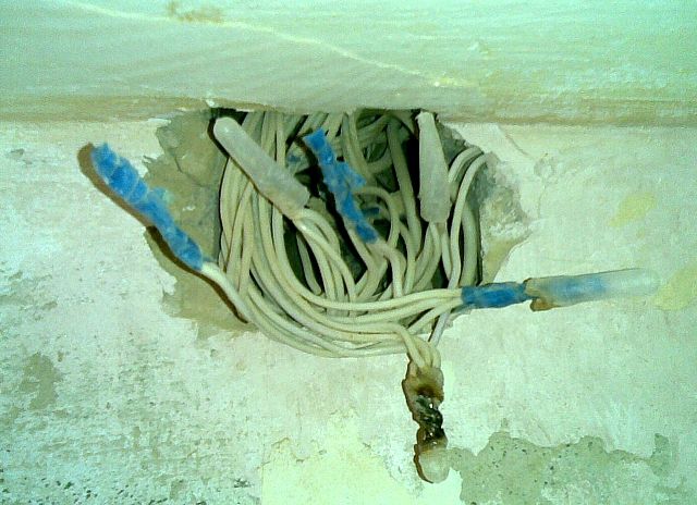
- Another amazing property: it would seem that the metal is very resistant to corrosion, but it was not so! If even a small amount of water gets on the conductor, then electrocorrosion processes are inevitable under the influence of electricity. Moreover, they may not be noticeable externally - in appearance, the entire conductor inside can be “corroded” so much that even a small one causes heating, sparking or failure. Sometimes any touch to such a wire leads to its breaking.

Compare with the picture above - is there a difference?
In other words, if you are serious about electrical issues, you should not hesitate to replace all the old aluminum wiring with on reliable copper. Its electrical parameters are even higher, its ductility is good (but not excessive), and does not change with time or with use under heavy loads. The cost of copper wires is, of course, significantly higher, but the wiring in the apartment is done, as already mentioned, for decades to come, and saving on such issues is simply unreasonable. Along with the replacement, you can simultaneously resolve all issues with optimizing the placement of all elements of the home electrical network.
If the owner has purchased a new apartment, in a house that is built on the “do-it-yourself” principle, then there is nothing to think about - you need to carefully plan the entire apartment electrical network, taking into account your vision of the location of electrical appliances and furniture in the rooms, and do the wiring literally first of all - even before pouring floors, finishing walls and ceilings. Below in the text it will become clear why this is so.
A few more arguments in favor of not modernizing or repairing, but a major rework of the old wiring.
1. In the old days, grounding loops in residential buildings were not considered mandatory, and all intra-house networks were laid using the TN-C system, when the working zero and grounding were connected to a single wire (PEN) at the electrical substation. The only advantage of this approach is ease of installation and minimal consumption of material, since all sockets in the apartment were tangled exclusively with two wires - neutral and phase.

The TN–C system is “the day before yesterday” in electrical engineering
When a reboot or breakdown occurs, life-threatening voltage is very likely to appear on the metal casing of electrical appliances. Moreover, this type of contact connection does not allow residual current devices (RCDs) and some modern switching power supplies to operate correctly. Today, such a system is not used, in some places it is even prohibited by law, and it should definitely be changed to one of the more advanced systems: TN–S or TN–С–S.
TN-S is more often used in private homes that have their own. Although, in apartment buildings, grounding buses can be organized, connected by welding and passing from the external grounding loop to all floors.

But still, more often in multi-storey residential buildings the TN–С–S system is used, in which solidly grounded the neutral is divided into two conductors - the working neutral and the grounding circuit, directly in the access distribution panel.

In any of the last two cases, three contacts are already used for wiring - phase, neutral and ground. You can immediately mention the color marking of these wires - one must comply with current standards.

Please note that the color of the phase wire may vary. But the neutral and grounding ones have a mandatory color, so that it cannot be confused during electrical installation work.

By the way, several phase conductors can be contained in one cable. They will differ in color from each other, but at the same time, two conductors will still be distinguished by their mandatory coloring - “working zero” and “ground”.
Many modern electrical appliances are equipped with a three-pin plug. So, an important clarification needs to be made. When installing new sockets, owners, of course, try to install three-pin ones as well. However, if your apartment has not yet installed electrical wiring according to the TN-S or TN-C-S schemes, then in no case should you make jumpers between the neutral contact and the ground contact directly on the socket.

If the life and health of your family and friends are not indifferent to you, never do such “grounding”!!!
What can be done at the switchboard level - absolutely unacceptable right at the connection point. This will not only not give the desired effect, but will also dramatically increase the level of danger. The likelihood of electric shock or a fire hazard with such a connection is enormous! It is better not to have a ground connection at all than to organize something like this.
Better yet, install new wiring according to all the rules!
2. The second important argument is that the wiring principle itself, previously used in residential construction, is extremely imperfect. We are talking about the so-called “dosing” of the load. To understand, remember the old distribution boards. An electric meter, two circuit breakers (or fuses - plugs) - and that’s it. Two wires went into the apartment, were lost somewhere in the thickness of the wall, and from them branches were made in contact boxes for each lighting point or socket. In a word, just as thin branches extend from the trunk of a tree, so branches were made from the main wires. Again: from an economic point of view, this is beneficial, but in all other respects it does not stand up to criticism.
This system was literally swarming with twists on every branch, and any extra connection of wires is always a weak point in the wiring. If it was necessary to turn off the power to one of the rooms, it was necessary to turn off the power in the entire apartment. Even a minor accident, an accidental short circuit on one of the branches, led to the shutdown of the entire residential network. Well, if something serious happened (a cable break or burnout hidden in the wall), then finding an emergency area and carrying out repair work turned into a very difficult problem.

All this can be easily avoided if you organize a zoned wiring system - from the entry point, that is, from the apartment distribution panel, separate power lines with the required wire cross-section corresponding to the load are laid to each room, to every high power electrical appliance every a group of sockets or lighting. Yes, of course, you will need much more cable here, but the home electrical network will become convenient and safe to use, and will be easy to accommodate the necessary modernization or repair.
The Basics – Planning Your Home Electrical Network
So, the first step in any case is whether a major overhaul will be carried out. or the wiring will be laid in a new apartment, a diagram of the apartment electrical network is always being drawn up. And it’s best to do this yourself - no one except the owners can do it better.
Perhaps someone doubts their ability to carry out such planning. It’s okay - there’s no need to rush, we do everything consistently, step by step. And you will see that it is not that difficult at all.
First, you need to prepare a plan for your apartment. There may be several options here. Firstly, you can make a copy of the technical passport. Secondly, it should not be difficult for a real man to draw an approximate diagram (preferably, of course, to scale) on a regular sheet of paper. Thirdly, if you wish, you can find a standard design of the house in which the apartment is located. (Such a document may be in the DEZ, another operating or design organization. It is possible that the Internet will come to the rescue). And fourthly, modern computer engineering applications (CAD) allow you to quickly and accurately execute the desired drawing.
For example, let’s take a diagram of a one-room apartment, completed in literally 10 minutes in CAD. The procedure for planning an apartment electrical network with a different number and location of rooms does not change - the principles remain the same.

In this case, Room 1 is a combined bathroom, Room2 is an entrance hall, Room3 is a kitchen and Room4 is a living room.
It’s also a good idea to have a version of such a drawing with dimensions: it will then make it easier to determine the required quantity of cable products.

The same drawing - with dimensions to scale
In order not to be afraid of mistakes and some accidental damage to the drawing, you can print it out for yourself or make photocopies in the required quantity - for drafts, taking as a basis a “bare” diagram to begin with - only walls, windows and doors.

The initial “clean” diagram - we’ll start working from there
Now you need to imagine how existing pieces of furniture and electrical appliances for various purposes will be arranged in this area. There is no need to rush - it is necessary to take into account not only what has already been purchased and is awaiting installation, but also planned new products in the future at least by 5 ÷ 10 years. For example, children are growing up, and in a couple of years they will need to install a desk with a lamp, a computer, a TV, etc. in their room. There are future plans to install modern climate control equipment (air conditioning or convectors) in the living room, and sooner or later the housewife will want a dishwasher and a multifunctional oven in the kitchen.
Moreover, it is necessary to place all these pieces of furniture and household appliances on the diagram in the places where, with a certain degree of assumption, they will be installed. A very awkward situation will happen if, after completing the installation of new wiring, after a very short time, you have to take out the old extension cords! Why then was all this repair agony?
It would probably be reasonable to hold an “extended family council” on this matter in order to come to a common opinion on the interior design and filling of the premises. And now we turn to the drawing again - we begin to “put” everything in its place. There is no need to seek special principles regarding symbols here - this scheme is working. The main thing is to number all the items and devices, put them in a description - a table, and it is advisable to highlight on the diagram those that will require a mandatory connection to a power source, for example, by shading them in a different color (in the diagram considered for example, they are highlighted in red).
So, by room:

Let’s virtually “put” everything in its place
In the living room:
1 – folding sofa bed.
2 - bedside table with night light and connection point, for example, for a phone charger.
3 – air conditioning – split system.
4 – plasma TV with a home theater sound system, receiver or other digital television equipment.
5 – dining table with chairs.
6 - cabinets.
7 – a work area with a computer and peripherals.
Those points that require connection can be highlighted in the text.
In the kitchen:
8 - fridge.
9 – dining table with chairs.
10 and 11– work tables (tabletops) on which can be placed permanently or periodically kitchen appliances - microwave, multicooker, food processor, blender, electric kettle and others.
12 – electric stove with oven.
13 – washing.
14 - Dishwasher.
In the bathroom and toilet:
15 - washing machine.
16 – boiler.
17 – washing with spotlight and hair dryer connection point.
18 – toilet.
19 - bathroom.
In the hall:
20 - closet with additional spot lighting.
So, the main “consumers” are highlighted in the diagram. It is clear that backup sockets are also needed (for example, to turn on an iron, vacuum cleaner, other small household appliances) - their placement can also be provided so that they do not end up uselessly located behind massive pieces of furniture.
You can immediately mark the locations of the sockets on a separate blank “form”.
In this case, you can, of course, use any symbols that you understand. But if the owner wants his plan to become clear to an electrician, then it is better to use the icons accepted in the professional environment. Know them all - not at all necessary, the most basic ones will be enough. For example, those listed in the table:
| Symbol | What does it mean on the diagram |
|---|---|
 | Power shield |
 | Energy consumption meter |
| Single-pole circuit breaker | |
| Double-pole circuit breaker | |
 | Residual current device (RCD) |
 | Socket with protective earth contact, for flush installation |
 | Double socket, with protective grounding contact, for hidden installation |
 | Three-pole socket, with protective earthing contact, for open installation |
 | Double-pole socket, with protective grounding contact, increased moisture resistance (IP44 - IP55) |
| Single-key switch | |
| Two-gang switch | |
 | Block - two switches and a socket, hidden installation |
So, let’s place the sockets on the diagram:

Now is the time to think about lighting points. They can be placed in the center of the room (that’s when scaled dimensions will be needed), and in any order, emphasizing the illumination in one direction or another, or organizing several points (tiers) of illumination. In our case, place the lamps in the center of the rooms. And immediately mark the places for the switches. They are usually located inside the room (with the exception of bathrooms and, sometimes, kitchens). A typical installation location is near the door, on the lock side. Although this is not a dogma at all, the owner can himself determine the most convenient place, in his opinion. For example, you can place a block of switches in the hallway that will be used to illuminate the corridor itself, the bathroom, and even the kitchen.

Then, we “hang” the lamps and arrange the switches
We have decided on the placement, now we need to move on to planning the wire route. Here, various options are possible, depending on the degree of readiness of the premises in terms of construction, on the planned finishing methods, on the location of the entrance to the apartment, on the preferences of the owners themselves.
Video: Tips for planning an apartment electrical network
Methods for laying electrical wiring in an apartment
Let’s make a reservation right away - only apartment options will be considered, that is, with concrete or brick walls. If someone needs information about, he can get it in the corresponding publication on our portal.
So, what are the acceptable methods of laying power cables used in apartment conditions:
A. If the walls are in a “draft” version, and in the future they are planned to be covered with a layer of plaster or lined with plasterboard, then the wiring can be placed directly along the existing surface in corrugated plastic pipes (if the thickness of the future finishing layer allows it) or simply in an open form, provided that the cable has reliable double or triple insulation.

Video: option for laying wires along the walls of an apartment
B. If the plaster layer has already been applied to the walls, or it is planned to be too thin, unable to cover the cable routing, then you will have to make grooves in the wall to lay the wires in them.
This matter, of course, is very tedious and dusty, but sometimes there is nowhere to go - this approach is often the only option. When laying wires in such grooves, they are fixed in them either with plaster blotches or with special plastic dowel brackets inserted into the holes drilled for them.

The wire can be secured in the groove with a special bracket...

...or simply plaster “slaps”
The grooves cannot be cut in completely random places. There are certain rules in this regard - there are areas near window and door openings, external and internal corners, near gas mains, where making grooves and laying cables is unacceptable. Graphic information on this matter is in the diagrams below:


Be sure to pay attention to one essential detail. All hidden routes to sockets and switches from distribution boxes must be routed exclusively vertically. This can be explained very simply - it will not be difficult to trace the route of a wire covered with plaster without any special instruments.

There should be no ledges or turns, no “in a straight line” at an angle. There is no need to hope, saying “I will remember.” This is forgotten very quickly, and, in addition, another person can attempt to drill a hole or drive a nail. This could end very sadly.
When laying cables in grooves, you must also have in your arsenal a drill bit, which will be required for cutting out sockets for under sockets and distribution (socket) boxes.
Now let's talk about the main sections along which the wires will be laid from the distribution board to the wiring boxes.
1. The first option is exactly the same as described above, that is, horizontally along the upper edge of the wall, in a groove or in a corrugated pipe. This option is extremely labor-intensive and costly - for example, in order to supply power to an outlet at the opposite end of a large room, you will need to go around all the corners - a lot of cable will be needed.
2. If the floors of a new apartment or one undergoing major renovation have not yet been screeded, then the lines can be laid in plastic or metal pipes along the surface of the floor. Here you can lay routes to distribution boxes the shortest by . In the future, a screed or other floor covering will completely hide these cable ducts.


By the way, with such a “lower” location of apartment electrical wiring, in some cases you can do without making grooves altogether or reduce this operation to a minimum. To lay wires in such situations, special electrical skirting boards are often used, on which there are already mounted ones.

And that’s not all. A new trend is becoming widespread - special kits that include electrical engineering skirting boards, cable channels, distribution boxes, sockets and switches, others electrical fittings products.

Wiring kit - everything is thought out, down to the smallest detail
Of course, this approach is not applicable for all styles of room decoration, but it also has a right to exist. And, by the way, it is in ever-growing demand, as it reduces dirty and complex construction work to a minimum.
3. Another option that helps to significantly reduce wire consumption is to use the ceiling surface for laying main routes. This, of course, does not eliminate the need to make grooves for laying wires along the walls and sockets for installing sockets and boxes. But from the distribution panel to the mounting boxes, the wires can be attached to special clips directly to the ceiling, laying routes along the shortest distance. By the way, absolutely nothing prevents you from placing the junction boxes themselves also on the ceiling plane (although it will not be easy to get to them later if you need to carry out any repair or adjustment work).

The ceiling is a great place to place electrical wiring. Of course, subject to further decorative finishing
True, all this will be possible only if you plan to install a suspended or suspended ceiling that will hide the cable routing. In a word, if it is possible to install a suspended or suspended ceiling, you must definitely agree - a lot of electrical problems will simply “dissolve.” As a last resort, it is quite possible to come up with some original hanging structure along the wall, in which you can hide the laid wires.

We continue drawing up the diagram
Let's return again to our diagram - the points where power needs to be supplied are already marked on it, but the routes have not yet been laid. It's time to do this.
The reader has probably already understood how the lines are laid, and in relation to his apartment he will be able to decide whether it will be a wall laying, or whether it can be laid in some areas along the shortest path if a floor or flow plane is used.
In our example, the routes will run along the walls.
So, each room should have its own mounting box (at least one). It is located, as a rule, not far from the entrance of the line from the distribution panel to the room. It is more advisable to place the bathroom box in the corridor so that the contact connections in it are not once again exposed to high humidity.
In the diagram we will roughly mark the distribution boxes with orange circles.

We continue drawing up the diagram - we outline the location of the mounting boxes
We begin to “pull the wires” to each box from the farthest outlets. It is better not to place sockets in a loop, that is, in series - voltage drops may occur on the farthest ones if those located closer to the box are reloaded. It’s better not to skimp and lay your own cable for each.
By the way, if the sockets are placed “coaxially” on both sides of one wall, you can connect them with wires coming from the same box and located in the same groove (our example specifically shows this possibility - a socket in the living room and in the kitchen). Of course, this will allow you to save a lot on laying grooves. In this case, you can use one common cable - however, do not forget that the cross-section of the wire going to such a unit must correspond to the total possible load.
To make it easier to understand in the drawing, we will mark the wires to the sockets, for example, in red.

“Stretching wires” from boxes to sockets
Change the color of the pencil to green, and “lay” the wires responsible for lighting - from the wiring boxes to the switches and lamps.

The same applies to lighting - lamps and switches.
Now let’s draw a power distribution board on the diagram and lay “mainways” from it to solderable boxes. You can, of course, limit yourself to one cable for each room, which will power both the lighting and sockets. However, we have already talked about this; it makes more sense to divide them into two different streams. If, of course, they allow financial resources, since in this case more cable products, automatic machines, and RCDs will be required. In a word, it’s up to the owner to decide, since both options are, in principle, acceptable.
The diagram shows an option for combined wiring to provide power and lighting (thick blue lines from the panel to the distribution boxes).

Now it’s the turn of the lines from the distribution panel to the mounting boxes
And finally, one more nuance. For some devices that consume high power current, completely separate lines are laid from the distribution panel, having their own circuit breakers, RCDs, and wire routing grooves. They should not have any other connections, branches, etc. throughout their entire length. Very often such lines end not with an ordinary socket, but with a reinforced one of a special type. And in some cases, high-power electrical appliances are connected to the network not through sockets at all, but through those installed directly next to them
In our diagram we will draw separate power lines from the panel to the electric oven in the kitchen and to the boiler in the combined bathroom (thick purple lines).

We “connect” especially loaded lines (oven and boiler) and the entrance from the entrance. The scheme is ready!
And finally, let’s complete the diagram by drawing on it the general input into the apartment from the access switchboard
So, the scheme is ready, and you can begin to apply it practically. First of all, it will help you calculate how much and what kind of wire will be needed to install a new apartment electrical network.
You can move on to work “on the ground” - actually transfer the drawing onto the walls of the premises, already accurately determining the location of the boxes, the lines of the grooves, the installation points of sockets and switches - everything basic principles were agreed upon by us, the drawing is at hand - let's get to work!
Surely, when marking, questions will arise - what? There are no strict rules here, and the recommendations are described in detail in our publication specifically devoted to this problem.
Marking lines drawn on the walls and a scaled drawing will help you count the number of wires for each section. But what size wire will be required?
What cross-section of wires are needed for installation?
Any line in our diagram coming out of the distribution board is equipped with a circuit breaker of the appropriate power and a residual current device (RCD), with its own response parameters at a certain leakage current. Plus, a common circuit breaker and a common RCD must be installed for the entire apartment network. All these mentioned values directly depend on the total load on each selected area, and then they already give a general result for the entire apartment.
So, knowing enough exactly, what electrical appliances will be used in each section of the residential network, you can calculate the total load on it. For this purpose, the passport data of the devices (instruments) is taken, the probability of their simultaneous operation is taken into account, and the power consumption is determined by the usual summation. If there are no passports for products, then you can search for their data on the Internet or simply use the average power table of the most popular household appliances and devices:
| Type of electrical appliance | Approximate power consumption |
|---|---|
| Hydromassage bath (Jacuzzi) | 2000-2500 W. |
| Mini sauna stove | 10-15 kW |
| Warm floor | 0.7-1.5 kW |
| Home solarium | 1.5-2.5 kW |
| Split air conditioner | about 2500 W |
| Fan | up to 900 W |
| Lighting devices (depending on the lamps used and the number of horns) | 100 - 1000 W |
| Radio receiver (Music center) | 100-250 W |
| Desktop computer with LCD monitor + peripherals (printer, scanner, modem, router, etc.) | up to 800 W |
| TV | 100-200 W |
| Sound system "home cinema" | up to 750 W |
| Vacuum cleaner | up to 1200 W |
| Iron | 1000-2000 W |
| Electric massager | up to 300 W |
| Hairdryer | 500 - 1000 W |
| Gadget chargers | about 50 W |
To make the calculation, you can use a formula that allows you to determine the current consumption at each section of the network.
Icmind=Psum/unom
Icmind– total load current in a given section of the circuit.
Psum– the total power consumption of electrical appliances simultaneously connected to the circuit.
Unom– rated voltage in the network (in our case, this is household voltage 220 IN).
If, for example, an area is calculated where it is likely that a computer (750 W), a heater (1.5 kW), a table lamp 100 W will work simultaneously, and an electric kettle will be turned on periodically (another 1.75 kW), then we get a total power consumption reaching 4.1 kilowatts at peak load. Substituting this value into the formula, we obtain the current consumption in 18.6 A.
When carrying out professional calculations, they use more complex methods that take into account a lot of other nuances of the network (this applies more to a three-phase 380 volt network). In conditions of a not too branched and loaded single-phase home network, it is recommended to simply add another 5 amperes to the result obtained for insurance. As a result, in our example it turns out 18,6 + 5 = 23,6 ≈ 24 A
Now all that remains is to go to the table (shown below) and find the most acceptable cross-section of the copper cable, depending on what type of wire will be used.
| Copper core cross-section | ||||||
|---|---|---|---|---|---|---|
| solid wires | two-core wires | three-core wires | ||||
| single wire | bundle of two wires | bundle of three wires | bundle of four wires | single two-core wire | single three-wire wire | |
| 0.5 | 11 | - | - | - | - | - |
| 0,75 | 15 | - | - | - | - | - |
| 1,0 | 17 | 16 | 15 | 14 | 15 | 14 |
| 1,5 | 23 | 19 | 17 | 16 | 18 | 15 |
| 2,5 | 30 | 27 | 25 | 25 | 25 | 21 |
| 4,0 | 31 | 38 | 35 | 30 | 32 | 27 |
| 6,0 | 50 | 46 | 42 | 40 | 40 | 34 |
| 10,0 | 80 | 70 | 60 | 50 | 55 | 50 |
| 16,0 | 100 | 85 | 80 | 75 | 80 | 70 |
| 25,0 | 140 | 115 | 100 | 90 | 100 | 85 |
| 35,0 | 170 | 135 | 125 | 115 | 125 | 100 |
| 50,0 | 215 | 185 | 170 | 150 | 160 | 135 |
The load on the area in the example given is quite serious. According to the table, it turns out that either three single wires laid in a single bundle, each with a cross-section of 2.5 mm, or one three-core wire with a cross-section of 4 mm, can handle such a load.
This - more One argument in favor of the fact that it is recommended to lay its own cable to each outlet (socket block). Work with large cross-section wires, connecting them to electrical fittings devices or making their contact connections is very difficult due to the sharply increasing rigidity.
Is it so important to calculate this cross section? Maybe it makes sense to lay approximately the same wire in all sections?
Very important, and even from several points of view!
First. A wire that is too small may not fully cope with its task. It will begin to heat up, which over time will lead to damage to the insulation, failure of contacts on the terminals or in the twists. This is the straight path to a short circuit, that is, the cause of electric shock or fire.
Second. The owner was overzealous and laid wires of excessive cross-section. Just for fun, go to the store and compare prices for copper wires of the same brand, but of different cross-sections, for example, 1.5 and 2.5 mm. The difference will probably surprise you and encourage you to calculate the load so as not to pay extra for absolutely unnecessary, overpriced options.
The experience of qualified electricians who have changed the wiring in more than one hundred apartments makes it possible to roughly depict the home network in the following picture:

The diagram shows some possible sections of the residential network, indicating the recommended cable cross-section, the approximate total load, the rating of the circuit breaker and the response threshold (leakage current) of the RCD. Of the variety of cable products, most experts unanimously recommend VVGng (index H G g indicates that it is enclosed in non-combustible insulation).
This scheme is by no means a dogma. The method of network planning and its calculation, which you have read above, has not been canceled, since it is simply impossible to take into account all the nuances in each individual apartment.
By the way, this is especially true for the modern kitchen, which has recently become literally “stuffed” with electronics and electrical equipment. You just need to look at the table to see the range of functionality and power consumption of kitchen accessories.
| Type of household electrical appliance | Average power consumption | Features of connecting to power supply |
|---|---|---|
| Electric stove or hob | from 3500 to 12000 W | Individually routed power line |
| Electric oven | from 2500 to 10000 W | |
| Washing machine | from 1500 to 3000 W | |
| Water heater | from 2500 to 7000 W | |
| Dishwasher | from 1500 to 3500 W | |
| Microwave | from 700 to 2500 W | connection to a regular 16 A socket is allowed |
| Refrigerator (only at start-up) | from 500 to 2000 W | |
| Electric kettle | from 700 to 1500 W | |
| Kitchen processor | from 500 to 1500 W | |
| Bread maker, steamer, etc. | from 700 to 2000 W | |
| Toaster | up to 1000 W | |
| Kitchen hood | from 500 to 1500 W | |
| Waste shredder | from 400 to 1000 W |
To connect such a mass of equipment, you have to use remarkable imagination in terms of its location in the kitchen, and carry out scrupulous power calculations. Judge for yourself - how difficult it would seem to be to organize at least this arrangement of sockets:

The kitchen is a very special room in terms of electrical wiring.
And this, as they say, is not the most “sophisticated” option. However, if you sit down calmly with a piece of paper, a pencil and a calculator, everything can be calculated very clearly and efficiently.
So, the reader has learned to draw up a diagram, is familiar with the rules of calculations, basic principles He also already knows the laying of the cable part. You can safely get down to work, and let our portal’s articles help you in this, which will tell you in detail about techniques, types, connecting powerful electrical appliances and much more. All this is in sections and.
One final note. The author of this publication is fully aware that any electrical engineering teacher would give a “juicy deuce” for the quality of the graphic circuits produced, so perhaps there will be critical remarks about this in the comments. However, the goal was not to teach site visitors drawing techniques. The main thing is that the reader understands the principle, using which he can independently plan his home electrical network.
Video: basic concepts about self-installation of apartment wiring
All work on installing new and replacing old electrical wiring, regardless of where it will be done, in an apartment or a private house, in a country house or in a garage, requires a competent and thoughtful approach. It is necessary to begin this complex process by drawing up a power supply project, based on a thorough consideration of the plan for the arrangement of all electrical systems for the home. The project can be drawn up the old fashioned way on paper using colored markers, or done on a computer using a simple graphics program. In this article we will take a step-by-step look at how to draw up an electrical wiring diagram in an apartment and a private house.
Deciding on the location of furniture and equipment
Before drawing up a diagram, it will be important to take into account the layout of the premises, the planned arrangement of furniture and the placement of stationary electrical appliances. Places for installing electrical accessories in the room should be chosen so that they are not cluttered with sofas or cabinets and provide comfortable access to turning lights and electricity consumers on and off. It would be better if the discussion of this complex issue was brought to the family council.
The first step is to make a floor plan indicating window and door openings. In order to make it easier in the future to calculate the required amount of cable and wire, it is better to draw up a plan on a scale in compliance with the dimensions. The process of designing an electrical wiring diagram will be considered using the example of a one-room apartment. It is better to number the names of the premises on the plan and indicate the decoding separately.
Where: 1 – hallway, 2 – bathroom, 3 – kitchen, 4 – living room.
Optimal installation locations for sockets
After this, it is necessary to mark on the diagram the places where it is planned to place pieces of furniture and stationary electrical appliances. If household equipment is highlighted in red, this will greatly simplify the work on further drawing up the wiring diagram. It is recommended that all electrical items be numbered and recorded in a transcript: 1 - washing machine, 2 - dishwasher, 3 - electric stove, 4 - acoustic center, 5 - TV, 6 - stereo system, 7 - personal computer.

Drawing up a plan for the location of furniture and equipment will allow you to determine the optimal installation points for sockets. Layout of sockets in the apartment:

For more information about what to pay attention to and how to place sockets in the kitchen and bathroom, read the articles:
To design a wiring diagram, we recommend using special programs. We have provided the best ones in a separate article!
Lighting scheme
In the classic version, ceiling lights should be located in the center of the room, the location of which is at the intersection of lines passing through the middle of the length and width of the room. In the hallway, made in the shape of the letter L, 2 lamps are installed.
When drawing the location of switches on the diagram, it is necessary to take into account that the door can open inward or outward, be right-handed or left-handed. An open door should not interfere with free access to it. Switches are usually located inside rooms. Exceptions are rooms with high moisture content, which include laundries, baths, and bathrooms. This is done to ensure electrical safety and safety of switching equipment.

The wiring plan provided shows that the bathroom light switch is located outside of the bathroom.
Routes for laying cables and wires
After determining the installation location of lamps, switches and sockets, it is necessary to draw up a diagram of the electrical wiring routes; this design phase is the main part of the work. The wiring diagram and installation is greatly simplified if you have suspended ceilings in your house or apartment. In this case, the wires are laid in corrugated pipes and attached to the rough ceiling.
In order to save wire, wiring routes are selected according to the shortest distance. A wire is laid in the grooves under the plaster, connecting the distribution boxes with switches and sockets. With the standard option for arranging ceilings, electrical wiring is laid in pre-punched grooves along the walls of the room. To connect lighting fixtures, the wire is passed through the ceiling channels. An example of laying a cable line, in accordance with existing standards, is provided in the diagram: 
Drawing up a plan for the electrical wiring route should begin from the farthest point of the electrical network. In this case, it will be a double socket in the hall; it must be connected to a distribution box, which should be installed at the entrance to the room. Then the route of the wire connecting the second outlet is plotted on the diagram.

The lighting network will consist of wires, the first of which runs from the box to the switch, the second, connected to the ceiling lamp, is laid in the channel of the floor slab. The distribution box in the hall receives power via two wires from a distribution board installed in the hallway. It is also necessary to provide, if possible. In this case, the wiring will be three-wire.
Using this principle, you need to draw up a wiring diagram for the remaining rooms. To complete the picture, we can assume that a suspended ceiling is installed in the kitchen. In this case, the electrical wiring will be laid in corrugated pipes, secured with dowels with nails to the concrete floor slab, the routes for its installation will be selected taking into account the shortest distance. Descents to electrical fittings will be made under plaster.

We should not forget that the power supply to the premises is carried out by at least two groups of wires, one of which provides power to the power network, the other is intended for the lighting network. We talked about this in more detail in a separate article.
You can save a lot if you connect the sockets together with a “loop”, bypassing the distribution boxes. Experienced electricians do not recommend practicing this connection method, due to the high current load on the sockets. In addition, when using this connection method, the failure of one outlet can cause a blackout of the entire power network.