The peculiarity of this circuit is that by turning the control knob you can change not only the output voltage, but also its polarity. Adjustment is made in the range from +12V to -12V.
Power supply circuit with polarity adjustment
Essentially, these are two separate voltage stabilizers - positive and negative with a common regulating resistor R5.
The transformer for the source is also required with double winding.
When the resistor R5 slider is in the middle position, both stabilizers are closed and the output voltage will be zero. When the engine is moved in one direction or another, one of the adjustable stabilizers will open - either “positive” or “negative” and, accordingly, the output voltage will change.
The capacitances of capacitors C1 and C2 should not be less than 1000 µF. Instead of transistors KT816 and KT817, you can use more powerful ones - for example, KT818 and KT819. The power of the power source itself directly depends on the power of the transformer used.
The transformer must have two output windings of at least 12 Volts each.
Instead of the KTs405 diode assembly, you can use four simple diodes connected in a bridge.
When designing industrial devices that are subject to increased reliability requirements, I have more than once encountered the problem of protecting the device from incorrect polarity of the power connection. Even experienced installers sometimes manage to confuse plus with minus. Probably, such problems are even more acute during the experiments of novice electronics engineers. In this article we will look at the simplest solutions to the problem - both traditional and rarely used protection methods.
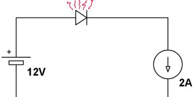
The simplest solution that suggests itself right away is to connect a conventional semiconductor diode in series with the device. 
Simple, cheap and cheerful, it would seem that what else is needed for happiness? However, this method has a very serious drawback - a large voltage drop across the open diode. 
Here is a typical I-V characteristic for direct connection of a diode. At a current of 2 Amps, the voltage drop will be approximately 0.85 volts. In the case of low-voltage circuits of 5 volts and below, this is a very significant loss. For higher voltage ones, such a drop plays a lesser role, but there is another unpleasant factor. In circuits with high current consumption, the diode will dissipate very significant power. So for the case shown in the top picture, we get:
0.85V x 2A = 1.7W.
The power dissipated by the diode is already too much for such a case and it will heat up noticeably!
However, if you are ready to part with a little more money, then you can use a Schottky diode, which has a lower drop voltage. 
Here is a typical I-V characteristic for a Schottky diode. Let's calculate the power dissipation for this case.
0.55V x 2A = 1.1W
Already somewhat better. But what to do if your device consumes even more serious current?
Sometimes diodes are placed in parallel with the device in reverse connection, which should burn out if the supply voltage is mixed up and lead to a short circuit. In this case, your device will most likely suffer minimal damage, but the power supply may fail, not to mention the fact that the protective diode itself will have to be replaced, and along with it, the tracks on the board may be damaged. In short, this method is for extreme sports enthusiasts.
However, there is another slightly more expensive, but very simple and devoid of the disadvantages listed above, method of protection - using a field-effect transistor. Over the past 10 years, the parameters of these semiconductor devices have improved dramatically, but the price, on the contrary, has dropped significantly. Perhaps the fact that they are extremely rarely used to protect critical circuits from incorrect polarity of the power supply can be largely explained by the inertia of thinking. Consider the following diagram: 
When power is applied, the voltage to the load passes through the protective diode. The drop on it is quite large - in our case, about a volt. However, as a result, a voltage exceeds the cutoff voltage is formed between the gate and source of the transistor and the transistor opens. The source-drain resistance decreases sharply and the current begins to flow not through the diode, but through the open transistor. 
Let's move on to specifics. For example, for the FQP47З06 transistor, the typical channel resistance will be 0.026 Ohm! It is easy to calculate that the power dissipated by the transistor in our case will be only 25 milliwatts, and the voltage drop is close to zero!
When changing the polarity of the power source, no current will flow in the circuit. Among the shortcomings of the circuit, one can perhaps note that such transistors do not have a very high breakdown voltage between the gate and source, but by slightly complicating the circuit, it can be used to protect higher-voltage circuits. 
I think it will not be difficult for readers to figure out for themselves how this scheme works.
After the publication of the article, a respected user in the comments provided a protection circuit based on a field-effect transistor, which is used in the iPhone 4. I hope he will not mind if I supplement my post with his find. 
A controlled constant stabilized current source with good dynamic characteristics allows you to change the magnitude and polarity of the output current under the influence of the input control voltage. The source can be part of various devices and systems. The accuracy of the output current matching the input control voltage allows the source to be used for critical applications. The operation of the current source can be explained using the example of controlling an LED indicator.
Using a current source to control LEDs
It is more convenient to change the brightness of LEDs by adjusting the current flowing through the LED, rather than the voltage applied to the LED. Using a controlled source of stabilized current, you can change and adjust the brightness of conventional or laser LEDs. By changing the polarity, you can select a group of working LEDs. With one polarity of the current, LEDs H1-H6 will light up, with the opposite polarity, LEDs H7-H12. If the LEDs have different colors, for example H1-H6 are red, and H7-H12 are green, it is possible to indicate the normal and critical value of the controlled value.
A source of constant stabilized current is necessary to regulate the magnitude of the constant magnetic field. The control voltage can come from a digital-to-analog converter of a specialized controller or other device.

Application of a current source to control electric motors
Using a direct current source that has the ability to change the direction of the current, it is quite simple to regulate the rotation speed and change the direction of rotation of the electric motor rotor. To transmit a command that sets the rotation parameters, one two-wire line is enough. Forward rotation occurs when the current polarity is positive on pin 1 and the current polarity is negative on pin 2 of the current source output connector U1.
Motor reversal occurs when the polarity of the control voltage and the resulting change in the polarity of the output current are changed. With the help of one source of current changing the direction, two electric motors can be controlled. With a positive polarity of the output current at pin 1, current flows through the diode VD2 and the electric motor M2 operates; with a negative polarity of the current at pin 1, current flows through the diode VD1 and the electric motor M1 operates. There is no motor reversal with this connection scheme.
A voltage-controlled current source is used in the transmission of analog signals. With this method of organizing communication, the current value is proportional to the analog value. The distortion of a signal transmitted by current by electromagnetic interference is significantly less compared to the conventional method of transmitting a signal by voltage.
The use of a current signal requires the installation of special current transmitting and receiving modules in the transmitting and receiving equipment. In this case, digital coding of the transmitted data can be eliminated. A voltage-controlled current source is used for smooth control of solenoid-based electromagnetic regulators in hydraulic systems. Based on a controlled current source, it is easy to build a universal device for charging batteries of different types.
Current source operation
The current generated by an ideal source is stable as the resistance of the connected load changes. To maintain the current value constant, the value of the source emf changes. A change in load resistance causes a change in the emf of the current source in such a way that the current value remains unchanged.
Real current sources maintain current at the required level over a limited range of voltage generated across varying load resistance. This range is limited by the power supply power of the current source. If it is necessary to maintain a current of 1 amp into a 20 ohm load, this means that the load will have a voltage of 20 volts. When the load resistance decreases or a short circuit occurs, the output voltage will decrease, and when the load resistance increases, the power supply must be able to operate at voltages above 20 volts.
Operation of the current source requires a power supply. A current stabilizer is connected in series with the power source. The output of such a device is considered as a current source. The power supply parameters of the current source are finite, this limits the maximum load resistance that can be connected to the current source. To ensure reliable operation, the power supply must have an overload reserve. The limited power supply limits the maximum current that the current source can deliver to the load.
The current source can operate with a load resistance close to zero. Shorting the output of the current source does not lead to a device failure or protection. If a short circuit occurs in the output of the current source caused by high humidity or careless handling of the equipment by maintenance personnel, after eliminating the causes of the short circuit, the device instantly returns to normal operation.
Controlled current source circuit
- Supply voltage………….100…260 V, 47…440 Hz
- Input voltage………….±10 V
- Output current………………….± 100 mA
- Load resistance……..0.1…120 Ohm
- Temperature range……-50…+75 ±С
- Conversion accuracy……0.5%

Simplified current source circuit
The operation of the circuit is based on the ability of the operational amplifier to change the output voltage of the operational amplifier so as to equalize the voltage at the inputs thanks to feedback circuits. The control voltage through resistor R1 is supplied to the inverting input of the operational amplifier and causes a change in the voltage at its output.
A change in voltage at the amplifier output causes current to flow through resistor R5 and the load. The output voltage is fed through feedback circuits to the inputs of the operational amplifier. The resistor resistances have values that provide the desired proportionality between the influence on the control voltage and the current through the load.
When a positive control voltage is supplied to the inverting input of the operational amplifier, a negative voltage is generated at its output. A current flows through the resistor and the load, creating a voltage across resistor R5. The potential at the junction of resistors R3 and R5 is lower than at the junction of resistors R4, R5 and the load.
Due to the fact that the total resistance of resistors R4 and R5 is equal to the resistance of R3, there is a potential at the output of the amplifier that compensates the control voltage at the inputs of the operational amplifier through feedback resistors. The amplifier output potential will drop as much as necessary to compensate for the effect of the positive control voltage on the inverting input of the operational amplifier.
Compensation for the effect of the control voltage on the inputs of the operational amplifier occurs depending on the voltage across resistor R5 caused by the flowing current. If the control voltage is fixed, then the feedback effect on the operational amplifier inputs depends on the voltage across resistor R5.
A change in load resistance causes a change in the potential at the non-inverting input of the operational amplifier through resistor R4. As the load resistance decreases, the potential at the non-inverting input of the operational amplifier decreases and the voltage between the inputs of the operational amplifier increases, which causes a decrease in the potential at the output of the amplifier. At the same time, the applied voltage decreases at a decreased load resistance, preventing the current from increasing.
The proportionality between the control voltage and the output current is established by the resistances of the resistors. The resistance of resistor R5 should be small; the output current flows through it, causing heating. Reducing resistance R5 expands the range of resistance of connected loads. The resistances of resistors R1 and R2 are equal, their values are chosen such that they eliminate overload of the control voltage source. Resistor resistances are calculated using the following formulas:
I = (U*R3)/(R1*R5)
- U - control voltage
- I - output current
One of the important parameters of any current source, and in our case a voltage-to-current converter, is the resistance range of the connected loads. The idealized model of the device provides the required current in the range of load resistance from 0 to infinity.
In real devices this is impossible and unnecessary, since the resistance of the wires, connector contacts, and elements of other circuits is added to the load resistance. The property of a current source to ensure the operation of the system regardless of the load resistance is very useful. Thanks to this property, it increases the reliability of the system in which the current source is involved.
The disadvantage of the current source is the power released at the output amplifier. In each case, you will need to choose a compromise between the load resistance margin and the heat generated at the output amplifier. To provide a wide range of load resistances, it is necessary to use a device power supply with a sufficient voltage margin.
with change in current direction
The practical implementation of the source is shown in the electrical circuit diagram. To accurately match the circuit calculations, the resistances are assembled from resistors connected in series or parallel. The output amplifier consists of transistors VT1 and VT2. With an output current of one hundred milliamps at a twenty-ohm load, the voltage will be two volts, across the regulating transistor the voltage drop is approximately 0.6 volts, and across resistor R5 the voltage drop is 0.1 volt. With a power supply of 15 volts, the voltage on one of the two transistors of the amplifier will be 15V-2.7V=12.3V, and a power of about 12.3V*100mA=1.23 W will be released in the form of heat.
Capacitor C4 is necessary to suppress interference induced on the line connected to the control input of the device, capacitor C5 prevents excitation of the circuit. Capacitor C1 reduces device interference into the power supply. Power is supplied from a network of 220 volts, 50 Hz.
Thanks to the DA1 pulse voltage converter, there are no voltage stability requirements for the power supply. Circuit breaker Q1 acts as a power switch and protects the 220-volt network from overload in the event of a device failure. H1 – power supply indicator. Transyl diode VD1 protects the power source from exceeding the mains voltage above a critical value. The voltage converter provides the device circuit with bipolar power, necessary for the operation of the operational amplifier and the formation of an output current of two polarities.
Circuit components
| Positional designation |
Name |
| Capacitors | |
| C1 | K73-16 0.01 µF ± 20%, 630 V |
| C2, C3 | C4 | 100 pF-J-1H-H5 50 Volt, f. Hitano | C5 | 0.47 µF-K-1N-N5 50 Volts, f. Hitano |
| Resistors | |
| R1, R2 | C2-29B-0.125-101 Ohm ± 0.05% | R3 | C2-23-0.25-33 Ohm ± 5% | R4 | C2-29B-0.125-101 Ohm ± 0.05% | R5 | 1 Ohm ± 0.01% Astro 2000 axial f. Megatron Electronic | R6, R7 | C2-29B-0.125-200 Ohm ± 0.05% | R8, R9 | C2-29B-0.125-10 kOhm ± 0.05% |
| Transistors and diodes | VT1 | TIP3055 f. Motorola |
| VT2 | TIP2955 f. Motorola |
| VD1 | Bidirectional transyl diode 1.5KE350CA f. STMicroelectronics |
| Circuits and modules | H1 | LED switch lamp SKL-14BL-220P “Proton” | DA1 | Voltage converter TML40215 f. TRACO POWER | DA2 | OP2177AR operational amplifier chip | Q1 | Automatic switch Ukrem VA-2010-S 2p 4A “Asko” |
Capacitor C1 can be of any type. An important requirement for this component is an operating voltage level of at least 630 volts. Capacitors C2...C5 can be used ceramic or multilayer. All resistors except R3 must have the highest possible accuracy. It is better to make resistor R5 a composite of four resistors with a resistance of 1 ohm.
Two circuits consisting of two 1 ohm resistors connected in series are connected in parallel. As a result, the total resistance is 1 ohm, and the power dissipation is quadrupled. Wire-type resistor R5 cannot be used. The DA1 switching voltage converter can be replaced with a bipolar power supply that provides an output current in each arm of 500 milliamps and a ripple level of no more than 50 millivolts.
To achieve high accuracy in converting control voltage to output current, the operational amplifier must have a low zero offset voltage. This is especially important for reducing the output current to zero under the influence of control voltage. With a slight decrease in accuracy, OP213 or OP177 microcircuits are suitable as a replacement for DA1. The use of powerful transistors at the output of the circuit increases the reliability of the device. Transistors must be installed on radiators.
The circuit can be used for other output currents and control voltages. To do this, you will need to make calculations using the formulas given earlier in the article. When performing calculations, you should take into account the possibility of using resistors from the standard range of resistances.
When checking the operation of the circuit, it is necessary to check with an oscilloscope over the entire range of voltages, currents and load resistance that there are no oscillations at the circuit output. If there are fluctuations, increase capacitance C4 or C5.
Platon Konstantinovich Denisov, Simferopol
[email protected]
The peculiarity of this power source is that by rotating the control knob you can not only change the output voltage, but also its polarity. Practically adjustable from +12V to - 12V. This is achieved thanks to the slightly unusual inclusion of stabilizers of a bipolar power supply, so that both stabilizers are regulated using one variable resistor.
The schematic diagram is shown in the figure. The rectifier is bipolar, made according to a standard circuit on a T1 transformer with a secondary winding tapped from the middle, a diode bridge VD 1 and capacitors C1 and C2. As a result, its output produces a bipolar voltage of +-16.., 20V. This voltage is supplied to two transistor stabilizers VT 1 and VT 3 (positive voltage regulation) and on transistors VT 2 and VT 4 (negative voltage adjustment). The difference from the standard bipolar circuit is that the outputs of the stabilizers are connected together, and that one common variable resistor is used to regulate the voltage R5. Thus, if the slider of this resistor is installed exactly in the middle, and the voltage across it relative to the common wire is zero, then both stabilizers are closed, and the voltage at the output of the circuit is also zero. Now, if the engine begins to move towards positive voltages (up in the circuit), the positive voltage stabilizer on the transistors begins to open VT 1 and VT 3, and a negative voltage stabilizer(VT 4 and VT 2) still remains closed. INThe result is a positive voltage at the output. Now, if the slider is moved in the direction of negative voltages (down the circuit), the positive voltage at the circuit terminal will decrease in the middle position R 5 the voltage will become zero. The positive voltage regulator will close. If the engine is moved further in the same direction, the negative voltage stabilizer on VT 2 and VT 4 (in this case, the positive voltage stabilizer will be closed) and the negative voltage at the output will increase.
The design uses a ready-made transformer"TAIWAN" with a power of 10 W, producing two alternating voltages of 12 V each on the secondary winding.
The capacitances of capacitors C1 and C2 should not be less than 1000 μF; it must be taken into account that the level of ripple at the output depends on them. Zener diodes can be any low-power voltage 12V. The KT817 transistor can be replaced with KT815, KT807, KT819. Transistor KT816 - on KT814, KT818. Transistors KT502 and KT503 can be replaced, respectively, with KT361 and KT315. You can use another rectifier bridge, for example KTs402, or assemble it from diodes like D226 or KD105.
Transistors VT 1 and VT 2 need to be placed on small heat sinks.
The peculiarity of this power source is that by rotating the control knob you can not only change the output voltage, but also its polarity. In practice, the voltage is regulated from + 12 to 12 V. This is achieved thanks to the slightly unusual inclusion of stabilizers of a bipolar power supply, so that both stabilizers are regulated using one variable resistor. The schematic diagram of the source is shown in Fig. 2.25.
The rectifier is bipolar, made according to the standard circuit on transformer T1 with a secondary winding tapped from the middle, a VDI diode bridge and capacitors C1 and C2. As a result, its output produces a bipolar voltage. This voltage is supplied to two stabilizers on transistors VT1 and VT3 (positive voltage regulation) and on transistors VT2 and VT4 (negative voltage regulation).
The difference from the standard bipolar circuit is that the outputs of the stabilizers are connected together, and that one common variable resistor R5 is used to regulate the voltage. Thus, if the slider of this resistor is installed exactly in the middle, and the voltage across it relative to the common wire is zero, then both stabilizers are closed, and the voltage at the output of the circuit is also zero. If the engine begins to move towards positive voltages (up the circuit), the positive voltage stabilizer on transistors VT1 and VT3 begins to open, and the negative voltage stabilizer VT4 and VT2 still remains closed.
The design uses a ready-made transformer with a power of 10 W, which produces two alternating voltages of 12 V each on the secondary winding. The capacitances of capacitors C1 and C2 should not be less than 1000 μF; it must be taken into account that the level of ripple at the output depends on them.
Zener diodes can be any low-power ones with a voltage of 12 V. The KT817 transistor can be replaced with KT815, KT807, KT819. Transistor KT816 on KT814. Transistors KT502 and KT503 can be replaced, respectively, with KT361 and KT315. You can use another rectifier bridge, for example, KTs402, or assemble it from diodes like D226 or KD105. Transistors VT1 and VT2 need to be placed on small heat sinks.